A mig welding torch self-adaptive adjustment device for fillet welds of stiffener structures

An adaptive adjustment, fillet weld technology, applied in electrode support devices, welding equipment, welding rod characteristics, etc., can solve the problems of inconsistent welding foot size, insufficient gas protection, unable to form welds, etc., to reduce labor and time costs. , Improve the efficiency of welding operation, the effect of simple and compact structure

Active Publication Date: 2020-07-03
CSSC HUANGPU WENCHONG SHIPBUILDING COMPANY
View PDF6 Cites 0 Cited by
  • Summary
  • Abstract
  • Description
  • Claims
  • Application Information

AI Technical Summary

Problems solved by technology

[0004] 1. The angle of the welding torch of the plate to be welded cannot be kept consistent, causing the size of the welding leg to be asymmetrical; if the angle changes too much, the temperature of the bottom plate will not reach the metallurgical bonding temperature, causing no fusion, so the angle of the welding torch needs to be adjusted manually;
[0005] 2. The path of the weld seam of the plate to be welded cannot be kept consistent, resulting in the welding arc molten pool not being on the weld seam to be welded, and the welding seam is not on the top or bottom, and the size of the welding leg is inconsistent, and the mechanical properties cannot be guaranteed;
[0006] 3. It may cause the arc to be too short and cause splashing. In severe cases, the contact tip may even come into contact with the molten pool, resulting in arc extinction and the trolley cannot move normally;
[0007] 4. It may cause the arc to be elongated, which will cause the weld to be unable to be formed, and a large number of pores will be formed due to insufficient gas protection

Method used


Image

  • A mig welding torch self-adaptive adjustment device for fillet welds of stiffener structures
  • A mig welding torch self-adaptive adjustment device for fillet welds of stiffener structures
  • A mig welding torch self-adaptive adjustment device for fillet welds of stiffener structures

Examples


Embodiment Construction

[0026] The preferred embodiments of the present invention will be described in detail below in conjunction with the accompanying drawings, so that the advantages and features of the present invention can be more easily understood by those skilled in the art, so as to define the protection scope of the present invention more clearly.

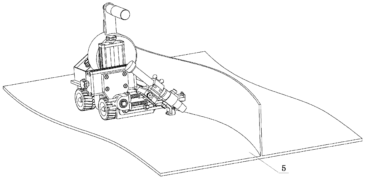
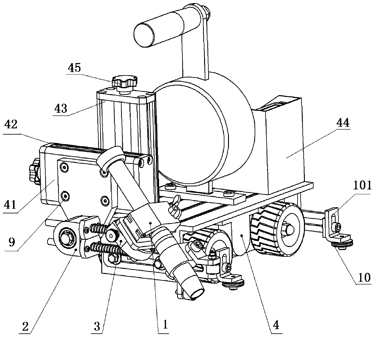
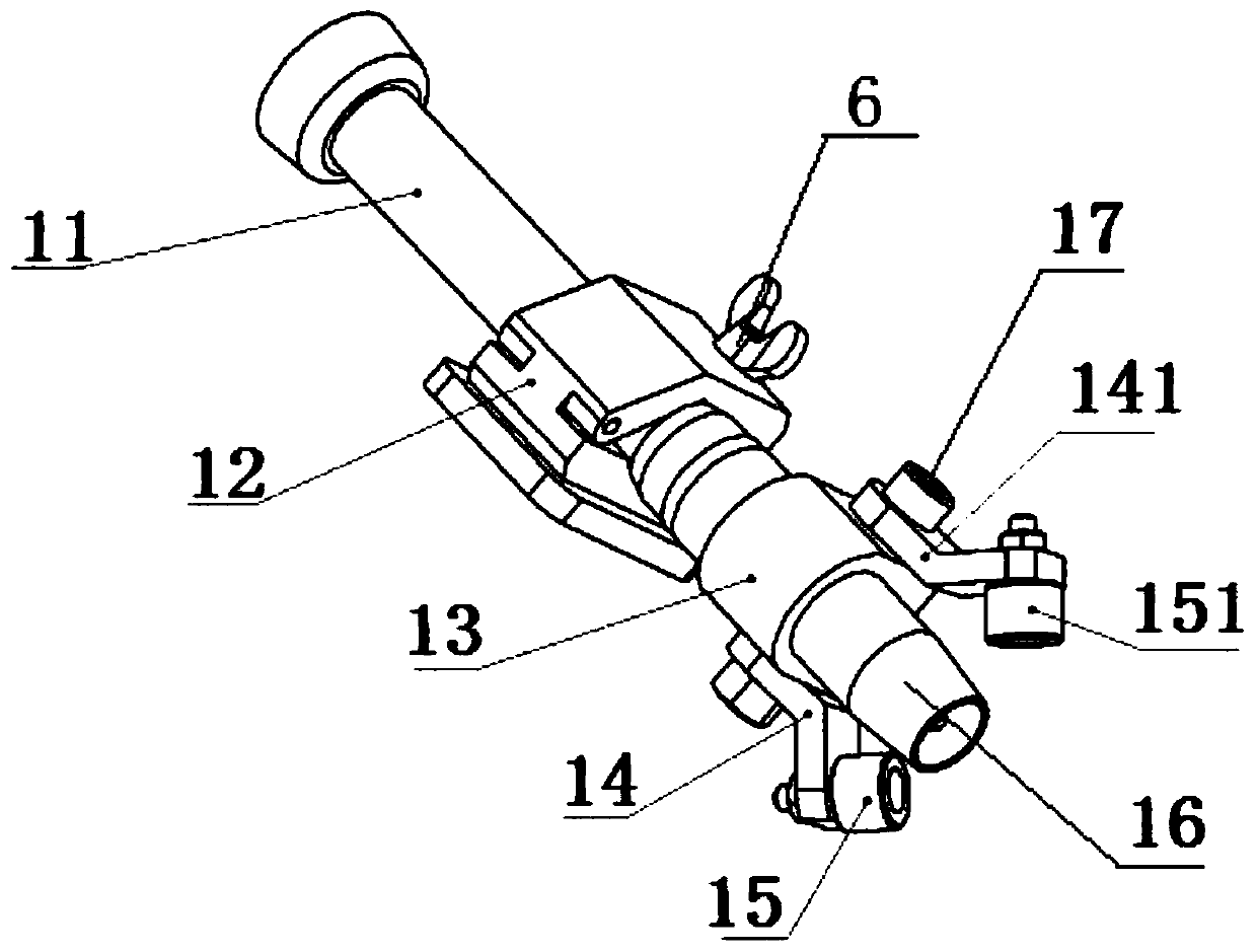
[0027] refer to Figure 1-5 As shown, the MIG welding torch self-adaptive adjustment device for fillet welds of stiffener structures of the present invention includes: a welding plate 5, and also includes a welding torch holder 1, a sliding table 2, a worm wheel base 3 and a MIG welding trolley 4, The welding gun holder 1 is rotatably arranged on the worm wheel base 3, and the worm wheel base 3 is obliquely connected with the slide table 2, and the slide table 2 is fixed on the slide block 41 by a plurality of bolts 9, and the slide block 41 can be horizontally Slidably arranged on the horizontal guide rail 42, the horizontal guide rail 42 can be...


PUM


Abstract

The invention discloses a MIG welding torch self-adaptive adjustment device for fillet welds of reinforced rib structures, which includes a welding plate, a welding torch holder, a slide table, a worm wheel base and a MIG welding trolley, and the welding torch holder is rotatably arranged On the worm wheel base, the worm wheel base is obliquely connected with the slide table, the slide table is fixed on the slide block, the slide block can slide horizontally on the horizontal guide rail, and the horizontal guide rail can slide vertically on the vertical guide rail Above, the vertical guide rail is fixed on the front of the MIG welding trolley, and the horizontal and vertical guide rails are respectively provided with locking pins. The invention realizes the manual initial positioning of the welding torch in the horizontal and vertical directions and the automatic adjustment and precise positioning of the height and angle between the welding torch and the fillet weld, and solves the problem that the arc cannot be automatically controlled when MIG welding is applied to irregular fillet welds problems, improve welding efficiency, welding quality and precision, and reduce labor and time costs.

Description

technical field [0001] The invention relates to the technical field of ship welding, in particular to a MIG welding torch self-adaptive adjustment device for fillet welds of stiffener structures. Background technique [0002] The hull structure of the aluminum alloy ship is welded by a large number of stiffener structures. For the fillet weld structure of the stiffener, the semi-automatic trolley MIG welding process is mainly used at present. This process is more suitable for the thickness of the stiffener structure greater than 5mm, because the plate is thicker, The deformation of the rib structure is small, and the semi-automatic trolley can be welded with a MIG welding torch to realize semi-automatic welding. When the thickness of the plate is 3-5mm thick, the rib structure will produce waves and bending deformation while welding, resulting in changes in the angle and distance between the MIG welding torch and the fillet weld to be welded, resulting in continuous changes ...

Claims


Application Information

Patent Timeline
Patent Type & Authority Patents(China)
IPC IPC(8): B23K9/173B23K9/28B23K9/12
CPCB23K9/126B23K9/173B23K9/28
Inventor 姜涛闫德俊蒋佳霖江小龙陈忠前杨占鹏王赛朱宇田鹏刘晓莉陈俞慨彭卫华陈景光董玉其杨飞飞肖体育路辉辉
Owner CSSC HUANGPU WENCHONG SHIPBUILDING COMPANY
Why Eureka
Try Eureka