
Droplet transfer control device and control method for gas shielded welding based on droplet resonance principle

A technology of gas shielded welding and droplet transfer, applied in the direction of manufacturing tools, welding equipment, welding accessories, etc., to achieve the effects of shortening the heating time, preventing short-circuit transition, and shortening the heating time

Active Publication Date: 2019-11-15
HARBIN INST OF TECH
View PDF8 Cites 0 Cited by
  • Summary
  • Abstract
  • Description
  • Claims
  • Application Information

AI Technical Summary

Problems solved by technology

[0004] Aiming at the many problems of gas shielded welding droplet transfer under low current, the present invention proposes a gas shielded welding droplet transfer control device and control method based on the principle of droplet resonance

Method used


Image

  • Droplet transfer control device and control method for gas shielded welding based on droplet resonance principle
  • Droplet transfer control device and control method for gas shielded welding based on droplet resonance principle
  • Droplet transfer control device and control method for gas shielded welding based on droplet resonance principle

Examples


specific Embodiment approach 1

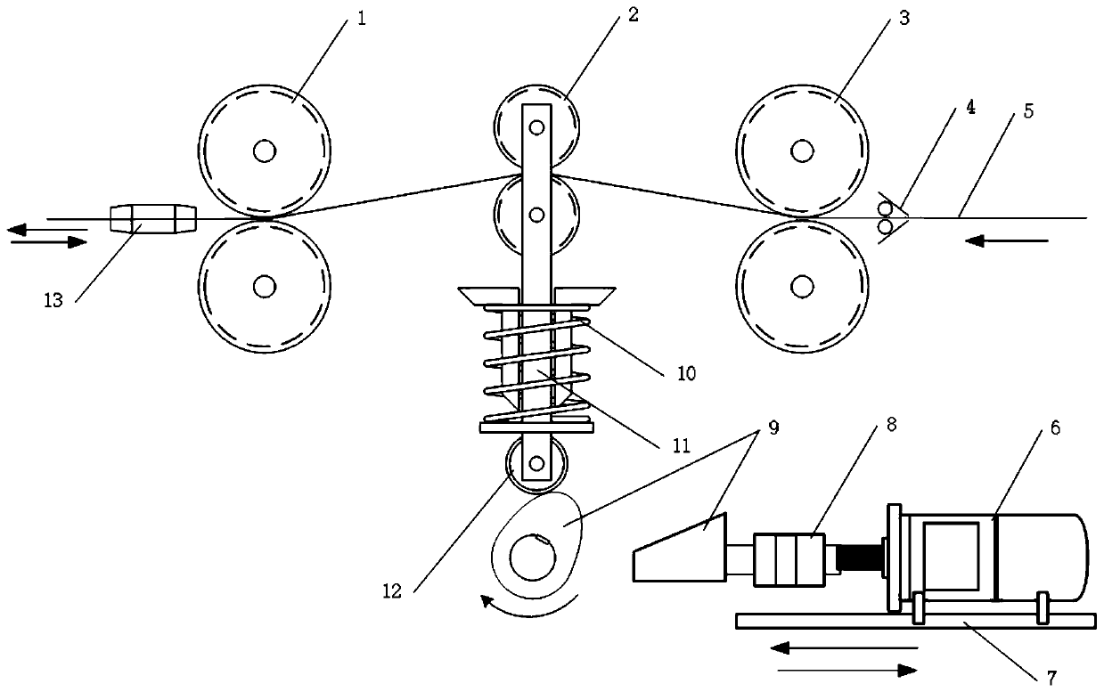
[0017] Specific implementation mode one: combine Figure 1 to Figure 6 Describe this embodiment, the gas shielded welding droplet transfer control device based on the principle of droplet resonance in this embodiment includes a first guide wire pair wheel 1, a second guide wire pair wheel 2, a third guide wire pair wheel 3, a cam Guide wheel mechanism, cam drive mechanism and contact tip 13, the first wire pair wheel 1, the second guide wire pair wheel 2, and the third guide wire pair wheel 3 are arranged in sequence from left to right, and the second guide wire pair wheel 2 is installed On the upper end of the cam guide wheel mechanism, the lower end of the cam guide wheel mechanism is connected with the cam driving mechanism, and the welding wire 5 passes through three pairs of guide wire pairs of wheels from right to left and is connected with the contact tip 13 one by one.

specific Embodiment approach 2

[0018] Specific implementation mode two: combination Figure 1 to Figure 6 Describe this embodiment, the cam guide wheel mechanism of the gas shielded welding droplet transfer control device based on the droplet resonance principle in this embodiment includes a return spring 10, a cam push rod 11 and a cam guide wheel 12, and the upper end of the cam push rod 11 It is connected with the second guide wire pair wheel 2, the lower end of the cam ejector rod 11 is connected with the cam guide wheel 12, the return spring 10 is set on the cam ejector rod 11, and the return spring 10 is located between the second guide wire pair wheel 2 and the cam guide wheel Between 12. Other components and connections are the same as those in the first embodiment.

specific Embodiment approach 3

[0019] Specific implementation mode three: combination Figure 1 to Figure 6 Describe this embodiment, the cam driving mechanism of the gas shielded welding droplet transfer control device based on the droplet resonance principle in this embodiment includes a high-speed servo motor 6, a slide rail 7, a shaft coupling 8 and a variable-diameter cam 9, and the high-speed servo The motor 6 is installed on the slide rail 7, and the high-speed servo motor 6 can move linearly along the slide rail 7. The rotating shaft of the high-speed servo motor 6 is connected with the variable-diameter cam 9 through the shaft coupling 8, and the wheel rim of the variable-diameter cam 9 is connected to the cam The guide wheel 12 contacts. Other compositions and connections are the same as those in Embodiment 1 or 2.


PUM


Abstract

The invention belongs to the field of welding and relates to a gas shielded welding molten drop transition control device and method, in particular to a gas shielded welding molten drop transition control device and method based on the molten drop resonance principle. The gas shielded welding molten drop transition control device and method based on the molten drop resonance principle aim at manyproblems existing in gas shielded welding molten drop transition under a low current. The gas shielded welding molten drop transition control device comprise first guide wire couplings, second guide wire couplings, third guide wire couplings, a cam guide wheel mechanism, a cam driving mechanism and a conductive nozzle. The first guide wire couplings, the second guide wire couplings and the third guide wire couplings are sequentially arranged from left to right, the second guide wire couplings are mounted at the upper end of the cam guide wheel mechanism, and a cam in the cam guide wheel mechanism is connected with the cam driving mechanism. A welding wire sequentially penetrates through the three pairs of guide wire couplings from right to left and then is connected with the conductive nozzle.

Description

technical field [0001] The invention relates to a gas shielded welding droplet transfer control device and a control method, in particular to a gas shielded welding droplet transfer control device and a control method based on the droplet resonance principle, belonging to the field of welding. Background technique [0002] With the continuous development of science and technology, the requirements for welding technology in various industries in our country are getting higher and higher, and the application of thin plates is increasing. Thin plates are more sensitive to the heat input in the welding process. Problems of burn-through, deformation and uneven weld formation. Therefore, it is necessary to reduce the welding current to reduce heat input when welding thin plates. However, under low current, the electromagnetic force and plasma flow force on the droplet are not strong enough, hindered by surface tension and spot force, the droplet transfer is a large (coarse) dropl...

Claims


Application Information

Patent Timeline
Patent Type & Authority Patents(China)
IPC IPC(8): B23K9/32B23K9/16
CPCB23K9/16B23K9/32
Inventor 高洪明张晓超董曼淑
Owner HARBIN INST OF TECH
Learn More