Molding device and method for manufacturing porous thin film through same
A technology of porous film and forming device, applied in the application, flat products, household appliances, etc., can solve the problems of high energy consumption, material waste, material pollution, etc., to improve production efficiency, reduce cost, and improve shape retention Effect
- Summary
- Abstract
- Description
- Claims
- Application Information
AI Technical Summary
Problems solved by technology
Method used
Image
Examples
Embodiment 1
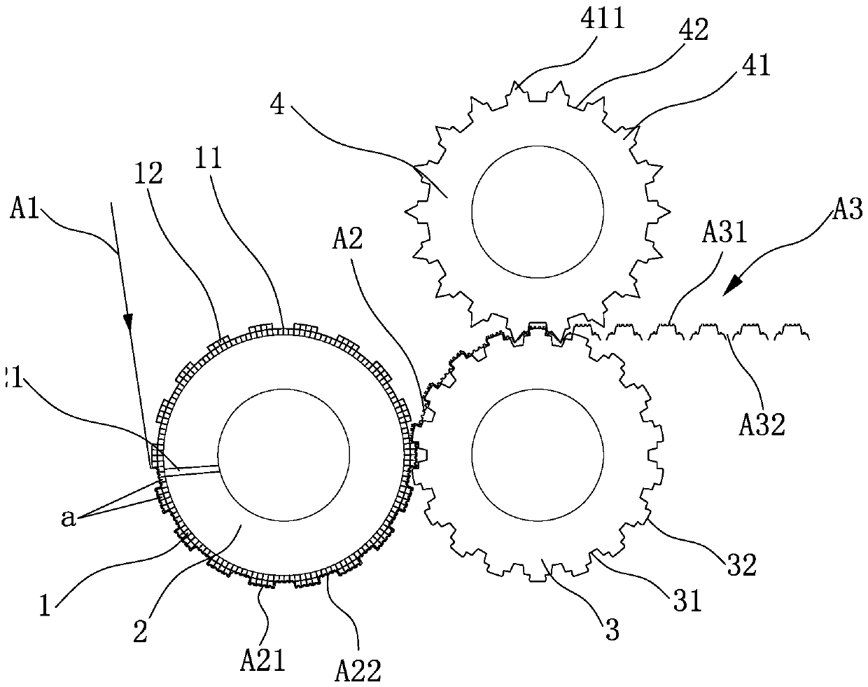
[0027] Cooperate Figure 3 to Figure 5 As shown, a forming device includes a forming cage 1, a vacuum forming drum 2, a concave roll 3 and a needle roll 4.
[0028] The forming cage 1 is a seamless cylindrical metal mesh cage with a recessed area 11 and a non-recessed area 12 on the surface, and both the recessed area 11 and the non-recessed area 12 on the forming cage 1 have through holes 13, Specifically, the surface of the forming cage 1 has 20 to 1600 through holes 13 per square centimeter, and the area of a single through hole 13 is 0.03mm 2 ~2.5mm 2, , the depression depth of the depression area 11 of the forming cage 1 is 0.1mm-0.8mm. In this embodiment, preferably, the surface of the forming cage 1 has 250 through holes 13 per square centimeter, and the area of a single through hole 13 is 0.15mm 2 , the recessed depth of the recessed region 11 is 0.4 mm. The forming cage 1 is set on the vacuum forming drum 2, and the vacuum forming drum 2 is connected with a va...
Embodiment 2
[0034] Cooperate Image 6 As shown, a forming device includes a forming cage 1, a vacuum forming drum 2, a concave roll 3 and a needle roll 4.
[0035] The forming cage 1 is a seamless cylindrical metal mesh cage with a recessed area 11 and a non-recessed area 12 on the surface, and both the recessed area 11 and the non-recessed area 12 on the forming cage 1 have through holes 13, Specifically, the surface of the forming cage 1 has 20 to 1600 through holes 13 per square centimeter, and the area of a single through hole 13 is 0.03mm 2 ~2.5mm 2, , the depression depth of the depression area 11 of the forming cage 1 is 0.1mm-0.8mm. In this embodiment, preferably, the surface of the forming cage 1 has 468 through holes 13 per square centimeter, and the area of a single through hole 13 is 0.1 mm. 2 , the recessed depth of the recessed area 11 is 0.5 mm. The forming cage 1 is set on the vacuum forming drum 2, and the vacuum forming drum 2 is connected with a vacuum pump. Al...
Embodiment 3
[0041] Cooperate Figure 7 to Figure 9 As shown, a forming device includes a forming cage 1, a vacuum forming drum 2, a concave roll 3 and a needle roll 4.
[0042] The forming cage 1 is a seamless cylindrical metal mesh cage with a recessed area 11 and a non-recessed area 12 on the surface, and both the recessed area 11 and the non-recessed area 12 on the forming cage 1 have through holes 13, Specifically, the surface of the forming cage 1 has 20 to 1600 through holes 13 per square centimeter, and the area of a single through hole 13 is 0.03mm 2 ~2.5mm 2, , the depression depth of the depression area 11 of the forming cage 1 is 0.1mm-0.8mm. In this embodiment, preferably, the surface of the forming cage 1 has 759 through holes 13 per square centimeter, and the area of a single through hole 13 is 0.08mm 2 , the recessed depth of the recessed region 11 is 0.6mm. The forming cage 1 is set on the vacuum forming drum 2, and the vacuum forming drum 2 is connected with a vac...
PUM
| Property | Measurement | Unit |
|---|---|---|
| Depth of depression | aaaaa | aaaaa |
Abstract
Description
Claims
Application Information
 - R&D
- Intellectual Property
- Life Sciences
- Materials
- Tech Scout
- Unparalleled Data Quality
- Higher Quality Content
- 60% Fewer Hallucinations
Browse by: Latest US Patents, China's latest patents, Technical Efficacy Thesaurus, Application Domain, Technology Topic, Popular Technical Reports.
© 2025 PatSnap. All rights reserved.Legal|Privacy policy|Modern Slavery Act Transparency Statement|Sitemap|About US| Contact US: help@patsnap.com


