Unilateral pressing coiling block non-glue tail sealing device

A technology of extrusion device and reel, which is applied in the direction of winding strips, transportation and packaging, and thin material processing, etc., which can solve the problems of fewer lamination layers, unfavorable sealing stability, and inconvenient operation.

Pending Publication Date: 2018-02-23
FOSHAN NANHAI DECHANGYU PAPER MASCH MFG CO LTD
View PDF5 Cites 5 Cited by
  • Summary
  • Abstract
  • Description
  • Claims
  • Application Information

AI Technical Summary

Problems solved by technology

The existing reel will be sealed with glue at the end after winding to maintain the stability of the reel. The sealing method with glue has the following three disadvantages: First, the reel must be glued before use. The process of tearing the tail will destroy the outer ring of the reel that is bonded to the tail end, so that part of the tail end cannot be used normally; second, because the glue has a certain permeability, it tends to stick to the inner paper in some cases. The user needs to tear off multiple layers before using it, which not only wastes materials, but also is inconvenient to operate; thirdly, a large amount of glue is used in the existing reel end sealing, which not only needs to increase additional material costs, but also glue is a It is a kind of chemical synthetic material, which has certain harmful components and is volatile. It will have a negative impact on the health of workers or users, whether in the production process or in use, and the use of a large amount of glue is not conducive to environmental protection.
However, the applicant only discloses its processing method in this patent, and does not disclose the specific equipment for realizing the method.
Although the patent applications with publication numbers CN101674993A and CN104755400A disclose mechanical means to form folds, they are inefficient and cannot form a tail seal at the end of the reel at one time
In addition, in the follow-up implementation process, the applicant found that the prior art still has the following deficiencies: when the tail end of the reel forms a press-fitting portion through the action of closing the die, due to the small contact area between the die and the reel, It will increase the difficulty of forming the pressing part. Even if the pressing part can be formed, the number of pressing layers is relatively small, which is not conducive to improving the stability of the tail seal; in order to ensure that the paper tail part of the reel can be pressed evenly, The clamping mold used must have high precision. However, in order to match the larger width of the reel, the clamping mold must also have a larger width, which will easily lead to flexible deformation of the clamping mold and affect the precision of the clamping mold. Then affect the sealing effect and the reliability of the sealing process

Method used


Image

  • Unilateral pressing coiling block non-glue tail sealing device
  • Unilateral pressing coiling block non-glue tail sealing device
  • Unilateral pressing coiling block non-glue tail sealing device

Examples


Embodiment 1

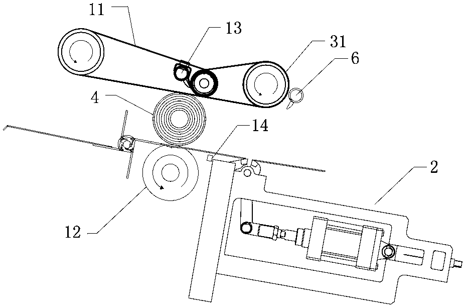
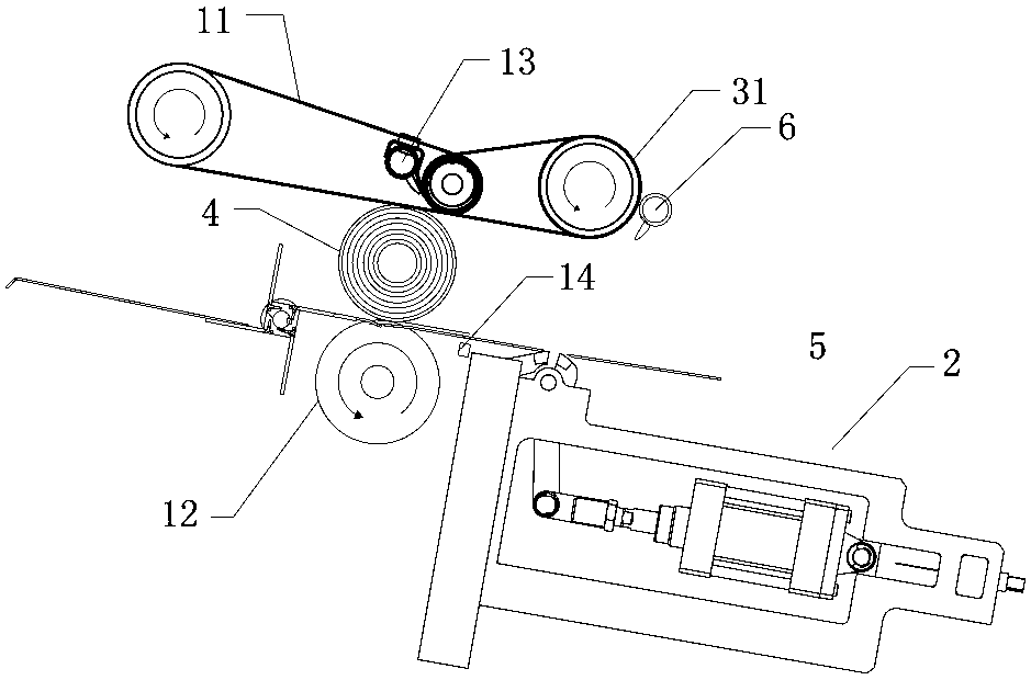
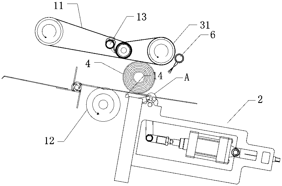
[0037] See attached figure 1 As shown, the unilaterally pressed reel glueless tail-sealing device in this embodiment includes a tail-seeking mechanism for finding the tail end of the reel 4, a tail-sealing mechanism 2 located downstream of the tail-finding mechanism, and a tail-sealing mechanism. The upper and lower pressing devices of the mechanism 2, the finishing mechanism and the air blowing unit 6 located downstream of the sealing mechanism 2.

[0038] In this embodiment, the tail-seeking mechanism includes a conveying belt 11, a roller 12, an air blowing pipe 13 and a detection head 14, wherein the conveying belt 11 and the roller 12 are relatively up and down and rotate in the same direction, so that a gap between the conveying belt 11 and the roller 12 A reel autorotation station is formed to make the reel 4 rotate in situ. Specifically, since the conveying belt 11 and the roller 12 rotate in the same direction with a very small speed difference, the linear speed of th...

Embodiment 2

[0053] see Figure 16 with Figure 17 As shown, the difference between the unilaterally pressed reel 4 glueless tail sealing device of this embodiment and the first embodiment is that the fixed clamping die 21a of this embodiment includes a plurality of small fixed clamps arranged in the axial direction of the reel 4 Clamping die 21a unit. The tail sealing mechanism 2 includes a fixed clamping die 21 a arranged axially along the drum 4 , a plurality of movable clamping dies 21 b arranged axially along the drum 4 , a plurality of drive units 23 , and multiple sets of clamps arranged axially along the drum 4 . Arm assembly, wherein, each group of clamping arm assemblies comprises frame 22, mutually hinged movable clamping arm 24b and fixed clamping arm 24a, small fixed clamping die 21a unit and movable clamping die 21b are arranged on fixed clamping arm 24a and movable clamping respectively The head of the arm 24b; the movable clamp arm 24b and the fixed clamp arm 24a are hing...

Embodiment 3

[0055] see Figure 18 As shown, the difference between the unilaterally pressed reel 4 glueless tail sealing device in this embodiment and the first embodiment is that the fixed clamping die 21a and the moving clamping die 21b in this embodiment are arranged oppositely, wherein the fixed clamping die 21a and the moving clamping die 21b The clamping mold 21a can be fixed on the support beam, and the driving unit 23 is connected to one side to push the movable clamping mold 21b. The driving unit 23 expands and contracts to drive the movable clamping mold 21b and the fixed clamping mold 21a to move unilaterally to realize the movable clamping mold 21b opens and closes with fixed clamping mold 21a.


PUM


Abstract

The invention discloses a one-sided press-fit reel glueless tail sealing device, which includes a tail sealing mechanism and an extruding device facing up and down, and the tail sealing mechanism includes a fixed clamping die arranged along the axial direction of the reel, A plurality of movable clamping dies arranged axially along the reel and a plurality of driving units, wherein each of the driving units correspondingly drives at least one movable clamping die; the driving unit drives the moving clamping die to move unilaterally toward the fixed clamping die Realize the mutual opening and closing of the movable clamping die and the fixed clamping die, and the extrusion device is used to squeeze the roll to the opening between the fixed clamping die and the moving clamping die so that the jaws of the fixed clamping die and the moving clamping die are embedded in the coil The outer peripheral surface of the drum is closed towards the fixed clamping die through the movable clamping die to squeeze the outer peripheral surface of the reel to form a pressing part.

Description

technical field [0001] The present invention relates to the production and processing equipment of roll-shaped materials, more specifically to the technical field of production and processing equipment of toilet paper rolls, and in particular to a single-side pressure-bonded roll glueless end-sealing device. Background technique [0002] The reel is a roll-shaped material formed by winding the web-shaped material, and the common forms are toilet paper rolls, plastic rolls, etc. Taking the toilet paper roll as an example, in order to maintain the stability of the roll during packaging, transportation, etc., the existing roll needs to be sealed at the tail end of the roll so that it will not fall apart. The existing reel will be sealed with glue at the end after winding to maintain the stability of the reel. The sealing method with glue has the following three disadvantages: First, the reel must be glued before use. The process of tearing the tail will destroy the outer ring ...

Claims


Application Information

Patent Timeline
Patent Type & Authority Applications(China)
IPC IPC(8): B65H19/29
CPCB65H19/29B65H2301/414425B65H2301/414436B65H2301/414446B65H2701/1924
Inventor 陆德昌
Owner FOSHAN NANHAI DECHANGYU PAPER MASCH MFG CO LTD
Why Eureka
Try Eureka