
Two-stage cantilever type axial-flow expander

An expander, cantilever type technology, applied in the field of expanders, can solve the problems of complex system, high unit speed, large axial thrust of the expander, etc., and achieve the effect of simple control system, high mechanical efficiency and low working speed

Pending Publication Date: 2018-02-23
陈贤
View PDF0 Cites 3 Cited by
  • Summary
  • Abstract
  • Description
  • Claims
  • Application Information

AI Technical Summary

Problems solved by technology

[0009] 1. Sealing problem;
[0010] 2. Lubricating oil pollutes the working gas;
[0011] 3. The speed of the unit is high and the reliability is poor;
[0012] 4. The axial thrust of the expander is very large, and the axial thrust that the unit can bear is very limited;
[0013] 5. Short service life, frequent repair and maintenance;
[0014] 6. The system is complicated and the cost is high

Method used


Image

  • Two-stage cantilever type axial-flow expander
  • Two-stage cantilever type axial-flow expander
  • Two-stage cantilever type axial-flow expander

Examples


Embodiment

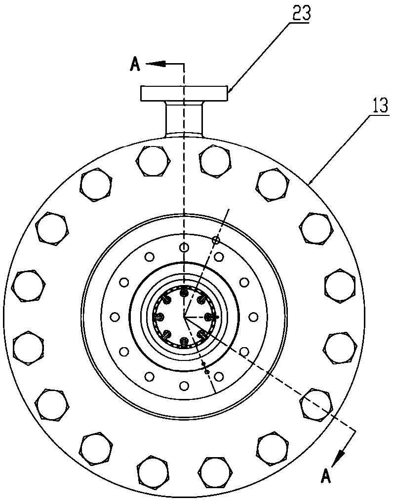
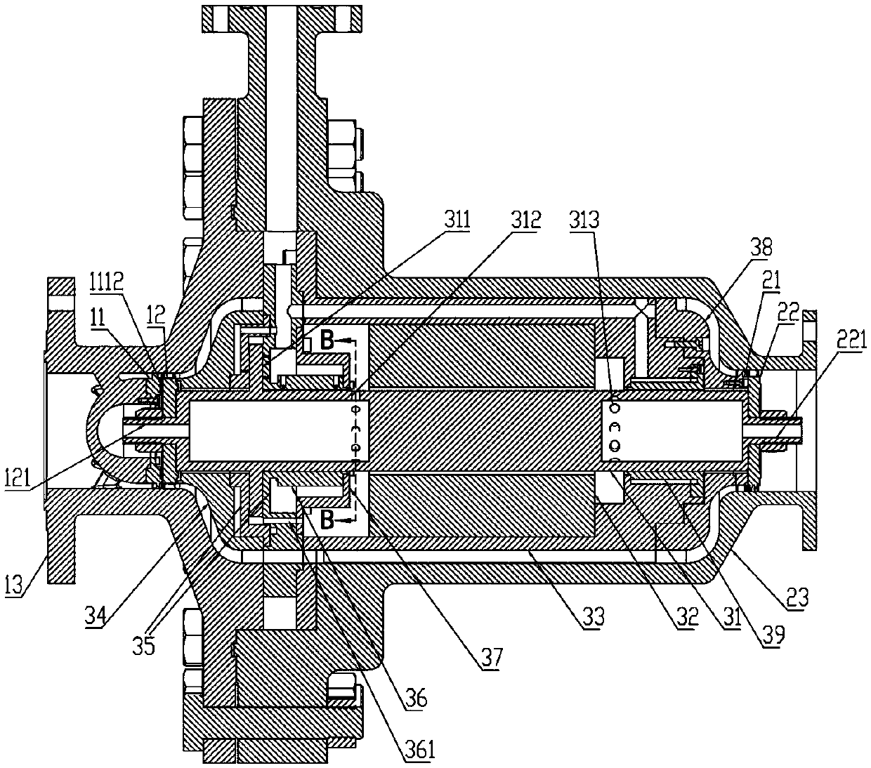
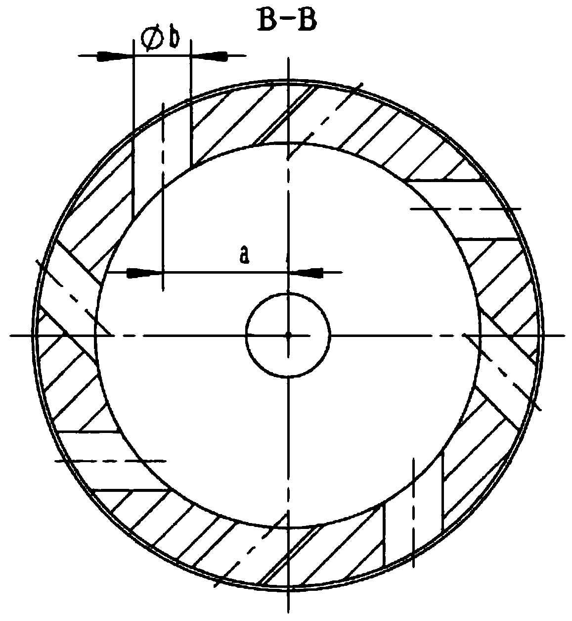
[0053] Such as figure 1 , figure 2 As shown, a two-stage cantilever type axial flow expander includes a first-stage expander, a second-stage expander, and a motor; the first-stage expander includes an intake housing 13, a first-stage nozzle ring 11 and The first-stage rotor impeller 12; the second expander includes the unit outer shell 23, the second-stage nozzle ring 21 and the second-stage rotor impeller 22; the motor includes a motor rotor 31 and a stator winding 32; the air intake casing The body 13 is arranged opposite to the unit outer shell 23 to form a cavity, and the motor rotor 31 is arranged in the cavity along the axis of the cavity, and the outer direction of the motor rotor 31 is along the direction from the intake shell 13 to the unit outer shell 23. An auxiliary thrust bearing housing 34, a motor housing 33 and a second-stage guide housing 38 are provided. The end face of the motor rotor 31 close to the intake housing 13 is coaxially provided with a first-sta...


PUM


Abstract

The invention discloses a two-stage cantilever type axial-flow expander. The two-stage cantilever type axial-flow expander comprises a primary expander, a secondary expander and a motor, wherein the primary expander comprises a gas inlet housing, a primary spray nozzle ring and a primary rotor impeller; the secondary expander comprises a unit housing, a secondary spray nozzle ring and a secondaryrotor impeller; the motor comprises a motor rotor and a stator winding; the gas inlet housing and the unit housing are oppositely arranged to form a cavity; the motor rotor is arranged in the cavity along the axis of the cavity; an auxiliary pushing bearing shell, a motor housing and a secondary guide housing are sequentially arranged on the outer edge of the motor rotor in a direction from the gas inlet housing to the unit housing; the end surface, close to the gas inlet housing, of the motor rotor is coaxially equipped with a primary input end; and the end surface, close to the unit housing,of the motor rotor is coaxially equipped with a secondary input end. The two-stage cantilever type axial-flow expander disclosed by the invention can effectively reduce rotation speed of the expanders through two-stage axial flow, improves reliability and efficiency of the motor and a frequency converter, and obtains a relatively high energy conversion rate.

Description

technical field [0001] The invention relates to the technical field of expanders in waste pressure and waste heat power generation systems, in particular to a two-stage cantilever type axial flow expander. Background technique [0002] At present, the pressure regulation of my country's natural gas transmission and distribution pipeline network adopts valve pressure relief, and the pressure energy is not utilized, resulting in a large amount of energy waste. my country's annual natural gas consumption is about 200 billion cubic meters, of which more than 130 billion cubic meters are self-produced and more than 60 billion cubic meters are imported. There are different degrees of pressure regulation links from the gas production port to the user. Using an expander instead of a pressure regulating valve to reduce pressure can recover the wasted pressure energy and convert it into mechanical energy for power generation. [0003] Natural gas is a flammable and explosive gas, onc...

Claims


Application Information

Patent Timeline
IPC IPC(8): F01D1/04F01D5/06F01D13/02F01D17/16F01D25/24F01D25/16H02K5/20H02K5/18H02K9/04
CPCH02K5/18H02K5/20H02K9/04F01D1/04F01D5/06F01D13/02F01D17/162F01D25/16F01D25/24
Inventor 陈贤
Owner 陈贤
Learn More