
Cooling water bypass valve of engine

A bypass valve and cooling water technology, applied to engine components, multi-way valves, valve details, etc., can solve problems affecting combustion efficiency and low intake air temperature, and achieve the effect of ensuring combustion efficiency

Pending Publication Date: 2018-02-23
ANQING CSSC DIESEL ENGINE
View PDF8 Cites 4 Cited by
  • Summary
  • Abstract
  • Description
  • Claims
  • Application Information

AI Technical Summary

Problems solved by technology

Before the mixed gas enters the engine, it needs to be cooled by the intercooler. However, the temperature of the intercooler will be different under different operating conditions of the engine. Under high load conditions, the intake air temperature is relatively high. The air cooler is used for cooling, and under low load conditions, it is generally below 25%. At this time, the intake air temperature is low. If the low-temperature water enters the intercooler to cool the air at this time, the intake air temperature will be too low, which will affect the combustion efficiency.

Method used


Image

  • Cooling water bypass valve of engine
  • Cooling water bypass valve of engine
  • Cooling water bypass valve of engine

Examples


Embodiment Construction

[0019] The present invention will be described in detail below in conjunction with the accompanying drawings.

[0020] In the description of the present invention, it should be noted that the terms "center", "upper", "lower", "left", "right", "vertical", "horizontal", "inner", "outer" etc. The indicated orientation or positional relationship is based on the orientation or positional relationship shown in the drawings, and is only for the convenience of describing the present invention and simplifying the description, rather than indicating or implying that the referred device or element must have a specific orientation, or in a specific orientation. construction and operation, therefore, should not be construed as limiting the invention. In addition, the terms "first", "second", and "third" are used for descriptive purposes only, and should not be construed as indicating or implying relative importance.

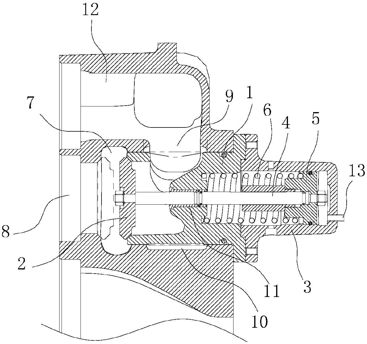
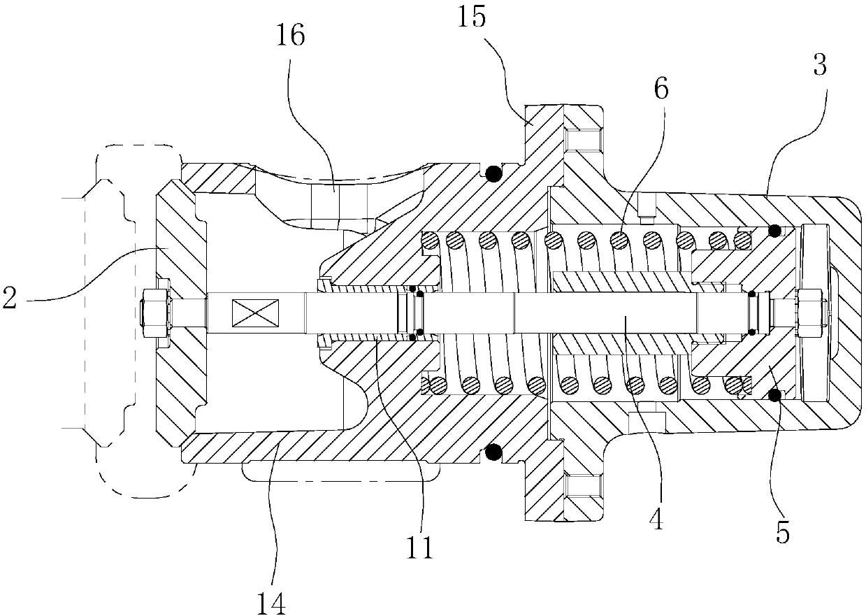
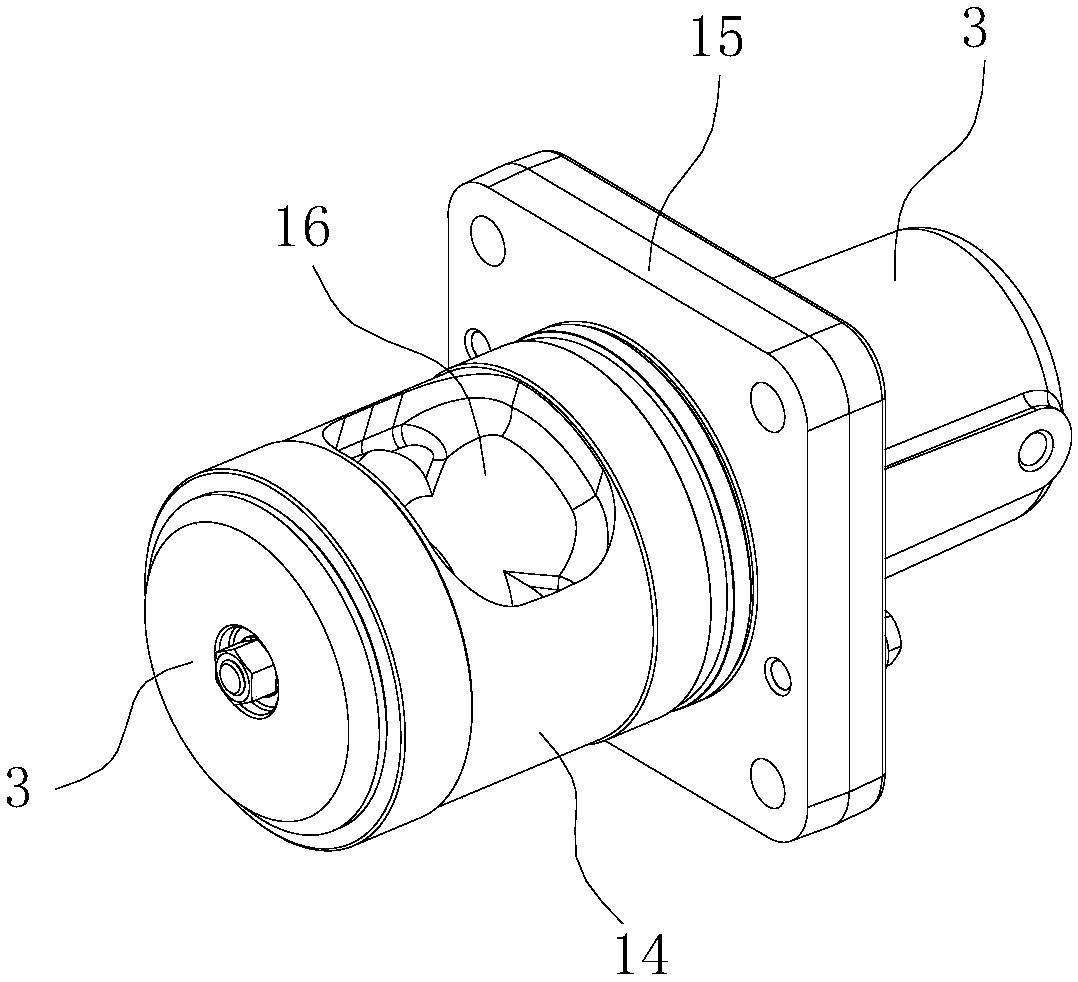
[0021] Figure 1-5 As shown, a cooling water bypass valve of an engine...


PUM


Abstract

The invention belongs to the technical field of ship engine producing and manufacturing, and particularly relates to a cooling water bypass valve of an engine. The cooling water bypass valve comprisesa valve cavity. The valve cavity is provided with a water inlet for cooling water inflow and two water outlets for cooling water outflow, wherein the water outlets include the first water outlet andthe second water outlet. A valve element is arranged in the valve cavity and movably arranged in the valve cavity. The valve element moves in the valve cavity and can control the water inlet to selectively communicate with the first water outlet or the second water outlet. The first water outlet communicates with a water inlet of an engine intercooler, the second water outlet communicates with anengine body cooling water cavity, and the water inlet communicates with a water outlet of an engine cooling water pump. The bypass valve can selectively control the low-temperature water to flow intothe intercooler according to needs, the intercooler can cool air to the adaptive temperature according to needs of various work conditions, and the combustion efficiency of the engine is ensured.

Description

technical field [0001] The invention belongs to the technical field of marine engine production and manufacturing, and in particular relates to a cooling water bypass valve for an engine. Background technique [0002] In order to improve the combustion efficiency of marine engines, the inventors provided a new engine air supply method, that is, the air is mixed with the exhaust gas of the engine breathing system and then passed into the piston cylinder for combustion support. This air supply method can effectively improve the combustion efficiency of the marine engine. fuel combustion efficiency. Before the mixed gas enters the engine, it needs to be cooled by the intercooler. However, the temperature of the intercooler will be different under different operating conditions of the engine. The air cooler is used for cooling, and under low-load conditions, it is generally below 25%. At this time, the intake air temperature is low. If low-temperature water enters the intercool...

Claims


Application Information

Patent Timeline
Patent Type & Authority Applications(China)
IPC IPC(8): F16K11/044F16K27/02
CPCF16K11/044F16K27/0263
Inventor 徐淳孙显李灿唐彬彬
Owner ANQING CSSC DIESEL ENGINE
Learn More