
Voltage regulator

A technology of voltage regulator and power supply voltage, which is applied in the direction of data processing power supply, measuring device, measurement flow/mass flow, etc. Consumption and other issues

Active Publication Date: 2018-02-23
SEMICON MFG INT (SHANGHAI) CORP +1
View PDF6 Cites 1 Cited by
  • Summary
  • Abstract
  • Description
  • Claims
  • Application Information

AI Technical Summary

Problems solved by technology

Among them, the power consumption of 20μA means that the circuit has strong anti-noise ability, but the power consumption is relatively large, which can be applied to various devices that are not sensitive to noise; the circuit with a power consumption of 5μA has weak anti-noise and is not suitable for high-speed equipment. For example: Central Process Unit (Central Process Unit, CPU), radio frequency (Radio Frequency, RF) circuit, etc.; low-power circuits with power consumption of 1 μA have weak noise immunity and are only suitable for low-speed devices
However, even a 1μA voltage regulator still has a large power consumption for wearable electronics
[0004] Therefore, in summary, the power consumption of the voltage regulator of the prior art is still high, especially for wearable electronic devices, and needs to be further reduced

Method used


Image

  • Voltage regulator
  • Voltage regulator
  • Voltage regulator

Examples


Embodiment Construction

[0028] As mentioned in the background section, the power consumption of the voltage regulator in the prior art is still high and needs to be further reduced to meet the needs of wearable electronic devices.

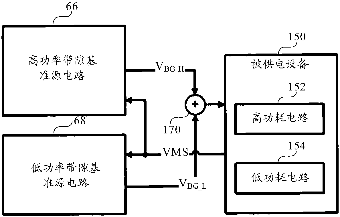
[0029] The inventors of the present application conducted an analysis of a prior art voltage regulator. figure 1 It is a schematic structural block diagram of a voltage regulator in the prior art. Such as figure 1 As shown, a low-power high-precision bandgap voltage reference circuit is disclosed in patent document US7579822. The reference circuit may include a high-power bandgap reference source circuit 66 and a low-power bandgap reference source circuit 68, which generate reference voltages respectively V BG_H and V BG_L , to supply power to the powered device 150 , wherein the powered device 150 includes a high power consumption circuit 152 and a low power consumption circuit 154 . The reference circuit can work in a first mode and a second mode. When the referenc...


PUM


Abstract

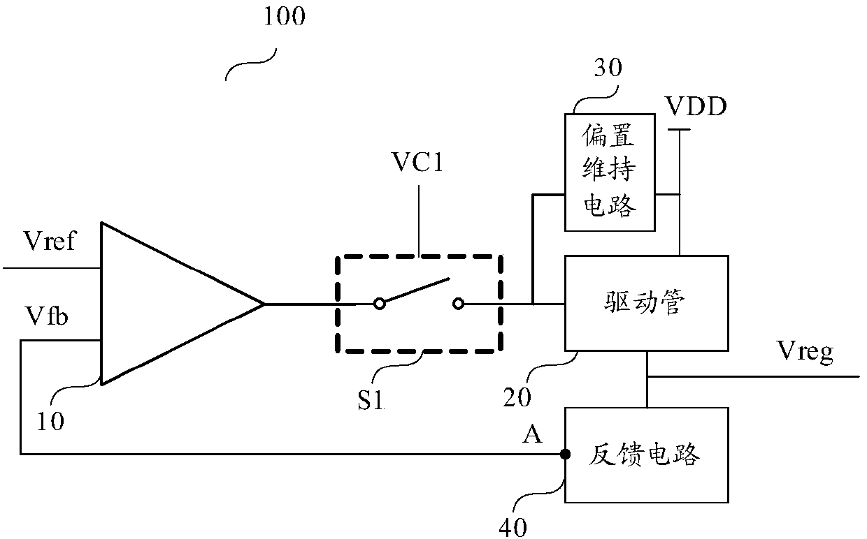
The invention discloses a voltage regulator. The voltage regulator comprises an error amplifier, a first switch, a driving tube, an offset maintenance circuit and a feedback circuit; a first input endof the error amplifier receives reference voltage; the first switch is closed or disconnected under the control of a first control signal; a first end of the first switch is coupled with an output end of the error amplifier; a control end of the driving tube is coupled with a second end of the first switch; an output end of the driving tube outputs regulation voltage; an input end of the drivingtube is coupled with a power supply; a first end of the offset maintenance circuit is coupled with the input end of the driving tube; a second end of the offset maintenance circuit is coupled with thecontrol end of the driving tube; when the first switch is controlled to be closed, the offset maintenance circuit is charged / discharged by the error amplifier; when the first switch is controlled tobe disconnected, the offset maintenance circuit is suitable for providing offset voltage for the driving tube; the feedback circuit is coupled with the output end of the driving tube and is suitable for carrying out voltage division on the regulation voltage so as to output a feedback signal at a feedback node; and the feedback signal is transmitted to a second input end of the error amplifier. The voltage regulator is capable of greatly reducing the circuit power consumption, is simple in circuit and is capable of saving the layout area.

Description

technical field [0001] The invention relates to the field of power supply design, in particular to a voltage regulator. Background technique [0002] With the technical evolution of wearable electronics, low power consumption is becoming more and more important. As a source of stable voltage, the voltage regulator (VoltageRegulator), if its power consumption can be reduced, can make the voltage regulator more suitable for Wearable electronic devices. The main reason for the high power consumption of the existing voltage regulator is that the voltage regulator is always on and has a certain static power consumption. Voltage regulators can be divided into many different types according to power consumption and noise immunity, but usually low power consumption will be accompanied by a decline in circuit noise immunity. Therefore, voltage regulators in the prior art generally include high power consumption and high noise immunity The circuit unit with low power consumption and...

Claims


Application Information

Patent Timeline
IPC IPC(8): G06F1/26
CPCG06F1/26
Inventor 杨家奇郭俊涛黄正太邓志兵黄正乙
Owner SEMICON MFG INT (SHANGHAI) CORP
Learn More