
Ka-band complete-polarization ultrathin frequency selective surface and antenna cover

A frequency selective surface, full polarization technology, applied in the direction of antenna, radiation unit cover, electrical components, etc., can solve the problems of difficult to achieve full polarization, poor out-of-band suppression, heavy weight, etc., to achieve good out-of-band suppression performance, Effect of RCS reduction

Inactive Publication Date: 2018-02-23
NAT UNIV OF DEFENSE TECH
View PDF1 Cites 5 Cited by
  • Summary
  • Abstract
  • Description
  • Claims
  • Application Information

AI Technical Summary

Problems solved by technology

[0004] Aiming at the shortcomings of the existing Ka-band frequency selective surface radome that it is difficult to achieve full polarization, poor out-of-band rejection, large thickness and heavy weight, etc., a fully polarized ultra-thin frequency selective surface radome with a thickness of only 0.5 mm is provided.

Method used


Image

  • Ka-band complete-polarization ultrathin frequency selective surface and antenna cover
  • Ka-band complete-polarization ultrathin frequency selective surface and antenna cover
  • Ka-band complete-polarization ultrathin frequency selective surface and antenna cover

Examples


Embodiment 1

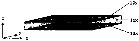
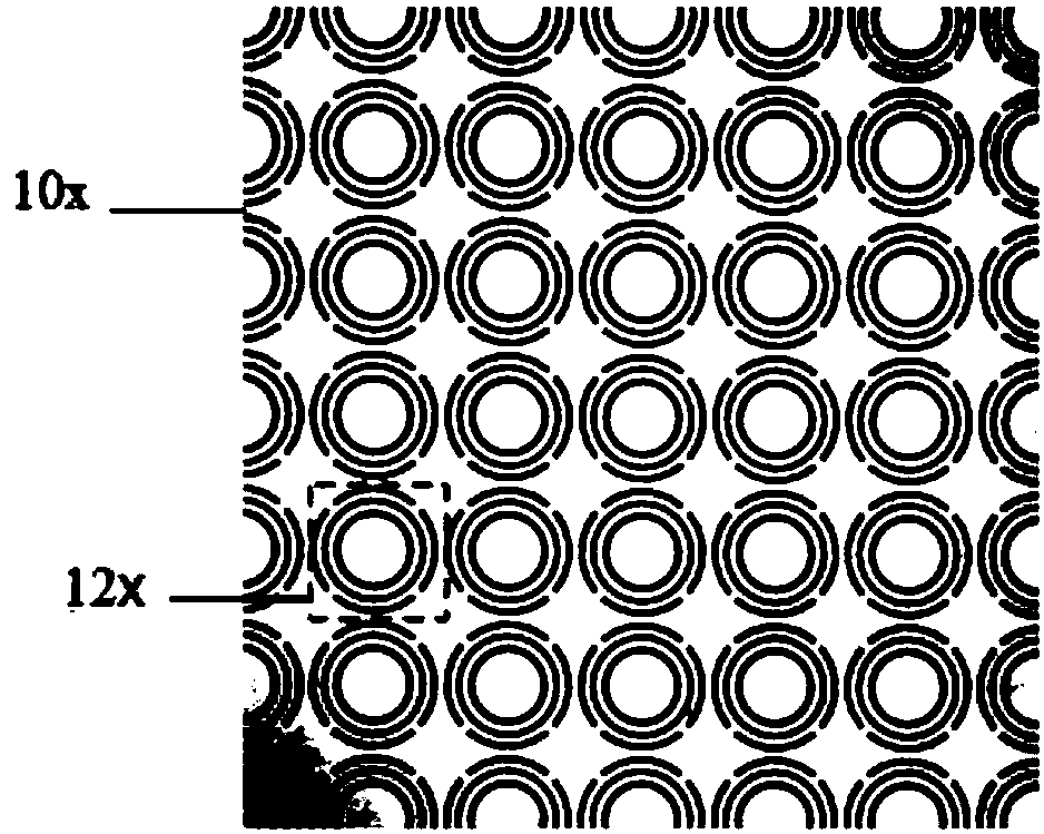
[0036] Such as figure 1 As shown, a Ka-band fully polarized ultra-thin frequency selective surface 10x is provided in this embodiment, comprising a dielectric substrate made of non-conductive material, and metal foil attached to the upper surface and the lower surface of the dielectric substrate layer; the metal foil layer on the upper surface contains several upper periodic micro-unit structures 12x arranged horizontally and vertically periodically, and the metal foil layer on the lower surface contains several lower periodic micro-unit structures 12x arranged horizontally and vertically periodically. Unit structure 13x; the geometric configurations of the upper and lower periodic micro-unit structures are the same; the lower-period micro-unit structure corresponds to the upper-period micro-unit structure.

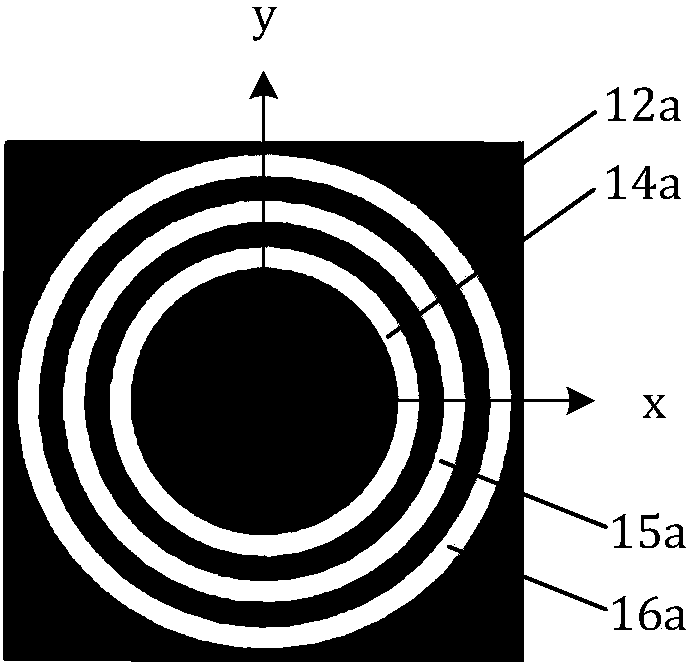
[0037] Such as figure 2 As shown, the micro-unit structure 12x / 13x of the upper / lower period is a square, including three ring-shaped gaps corroded by the circuit board...

Embodiment 2

[0050] This embodiment provides a radome made by using the Ka-band fully polarized ultra-thin frequency selective surface. The frequency selective surface employs as Figure 5 The third unit structure is shown. The side length of the cell structure is 4 mm. The radome includes 625 square unit structures, and its size is 100mm×100mm×0.5mm. The dielectric substrate of the radome adopts the sheet material of Rogers Company, the dielectric constant is 3.66, the loss tangent is 0.004, and the thickness is 0.5 mm.

[0051] Figure 11 Shown is the test platform where the frequency selective surface radome was tested. The test platform includes a flat radome 2, two Ka-band standard horn antennas 31, 32, and a vector network analyzer 4 connected to the antennas. The working frequency bands of the two Ka-band standard horn antennas 31 and 32 are from 26.5 GHz to 40 GHz. Wherein 31 is a transmitting antenna, 32 is a receiving antenna, 31 and 32 are respectively connected with two p...


PUM


Abstract

The invention provides a Ka-band complete-polarization ultrathin frequency selective surface. The Ka-band complete-polarization ultrathin frequency selective surface comprises a dielectric substrate and metal foil layers, wherein the metal foil layers are attached onto an upper surface and a lower surface of the substrate, the metal foil layers on the upper / lower surfaces comprises periodically-arranged upper / lower periodic micro unit structures, each unit structure is square and comprises three circular-annular gaps, four metal short-circuit gaps are loaded on an outer-side circular-annular gap and are uniformly arranged on a round ring, and the lower periodic micro unit structures are corresponding to the upper periodic micro unit structures. The invention also provides an antenna coverfabricated by employing the surface, and the antenna cover can be covered in a radiation direction of an antenna system. By the complete-polarization ultrathin frequency selective surface antenna cover, favorable rotation characteristic of the antenna within frequency bands of the Ka band being 33-37.5GHz can be maintained, free transceiving and communication can be achieved, meanwhile, good out-of-band rejection performance outside passband can be achieved, RCS of the antenna is reduced, and the purpose of hiding the antenna is achieved.

Description

technical field [0001] The invention belongs to the technical field of materials and radome, and in particular relates to a Ka-band fully polarized ultra-thin frequency selective surface and a radome. Background technique [0002] A frequency selective surface is an artificial periodic material. The electromagnetic properties of the original dielectric substrate are changed by designing the geometric shape of the metal foil coated on the surface of the dielectric substrate. By design, a frequency selective surface can transmit waves in certain frequency bands and reflect incoming waves in other frequency bands. Combining these frequency selective surfaces with the antenna can physically protect the antenna, act as a radome, improve the radiation performance of the antenna and reduce the radar cross section of the antenna to achieve stealth, etc.; it can also be made in the feed source The reflective surface that reflects electromagnetic waves in the working frequency band ...

Claims


Application Information

Patent Timeline
Patent Type & Authority Applications(China)
IPC IPC(8): H01Q15/00H01Q1/42
CPCH01Q15/0013H01Q1/42H01Q15/0026
Inventor 吴微微袁乃昌刘修瀚袁野马育红孟田珍周扬黄雷
Owner NAT UNIV OF DEFENSE TECH
Learn More