
Constant temperature control device of microwave synthesizer

A technology of constant temperature control and synthesizer, applied in electric heating devices, microwave heating, chemical instruments and methods, etc., can solve the problems of slow reaction speed, limited cavity volume, high temperature control requirements, etc., and achieve uniform and stable microwave temperature. , the effect of improving the response effect and improving the work efficiency

Inactive Publication Date: 2018-02-23
南京谱瑞生物科技有限公司
View PDF7 Cites 0 Cited by
  • Summary
  • Abstract
  • Description
  • Claims
  • Application Information

AI Technical Summary

Problems solved by technology

The microwave equipment currently used for scientific research is a traditional standing wave single-mode system, which is characterized by single-channel, one-way, high-density coupling, but the diameter of the single-mode energy interface is small, and the volume of the cavity is limited, and only 10-15ml can be placed in it. Another disadvantage is that the single-mode power is limited by the cavity. Due to the high density and small body, it is easy to produce instantaneous leakage and excessive thermal coupling to damage the reactants, resulting in research failure.
The chemical synthesis reaction is sensitive to the temperature requirements, and the temperature control requirements are very high. The rapid temperature rise in a short period of time will cause various side reactions in the reaction in the reactor body. The traditional microwave equipment has low control precision, resulting in impure reaction substances.
The microwave reactor in the traditional microwave equipment is put into the microwave in the static state, and the reaction is carried out in the static state, the reaction speed is slow, and the synthesis efficiency is low.

Method used


Image

  • Constant temperature control device of microwave synthesizer
  • Constant temperature control device of microwave synthesizer
  • Constant temperature control device of microwave synthesizer

Examples


Embodiment Construction

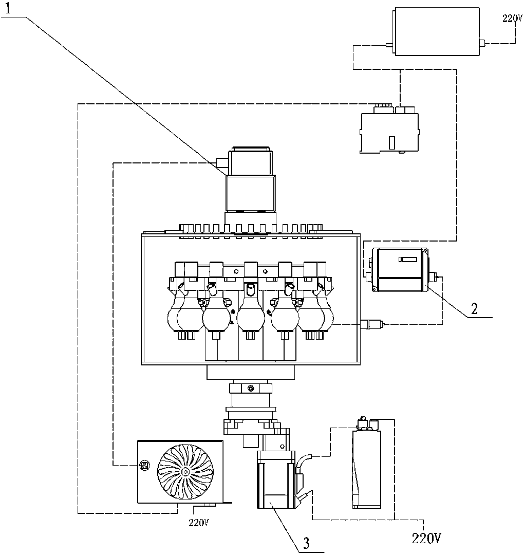
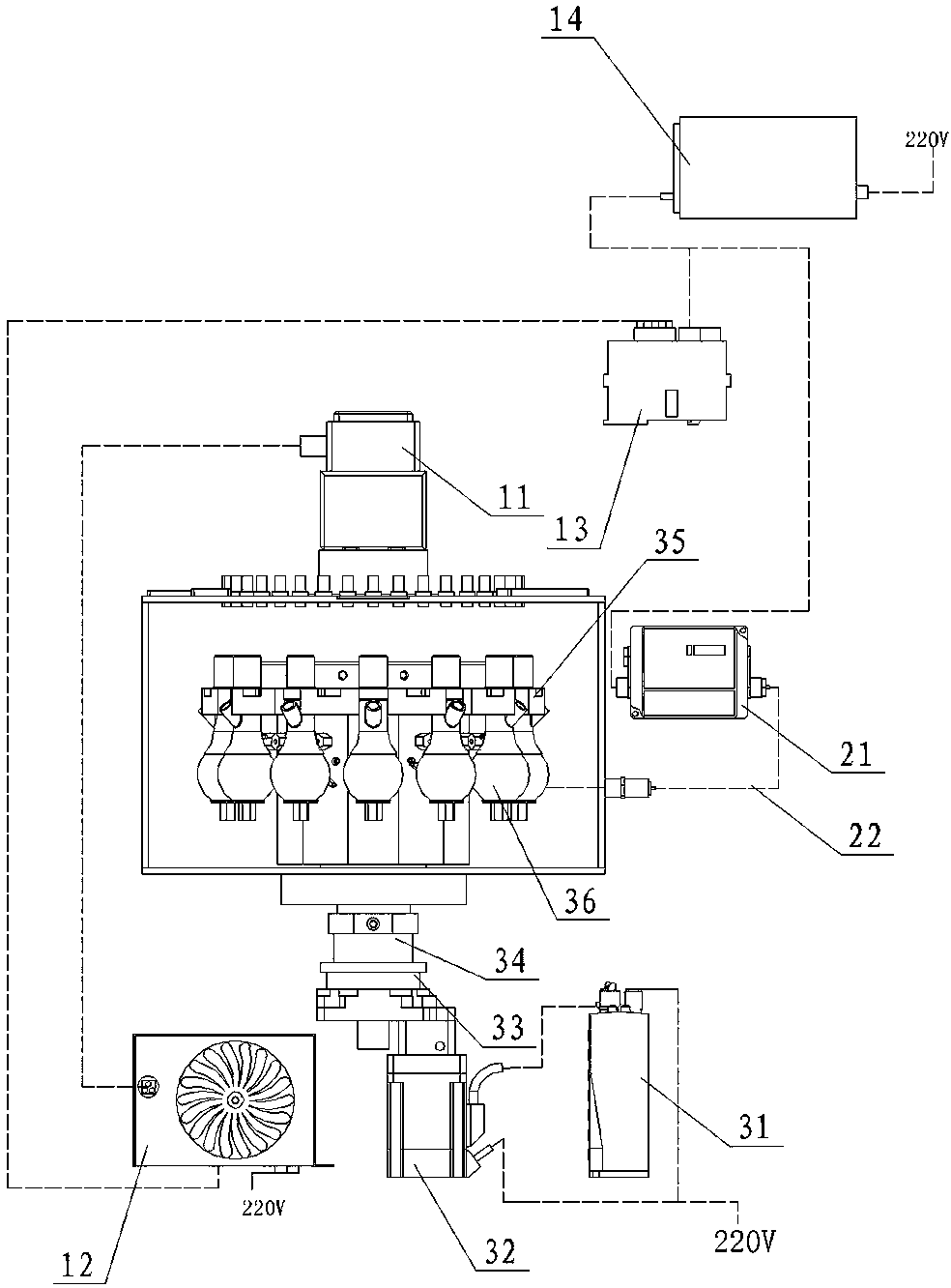
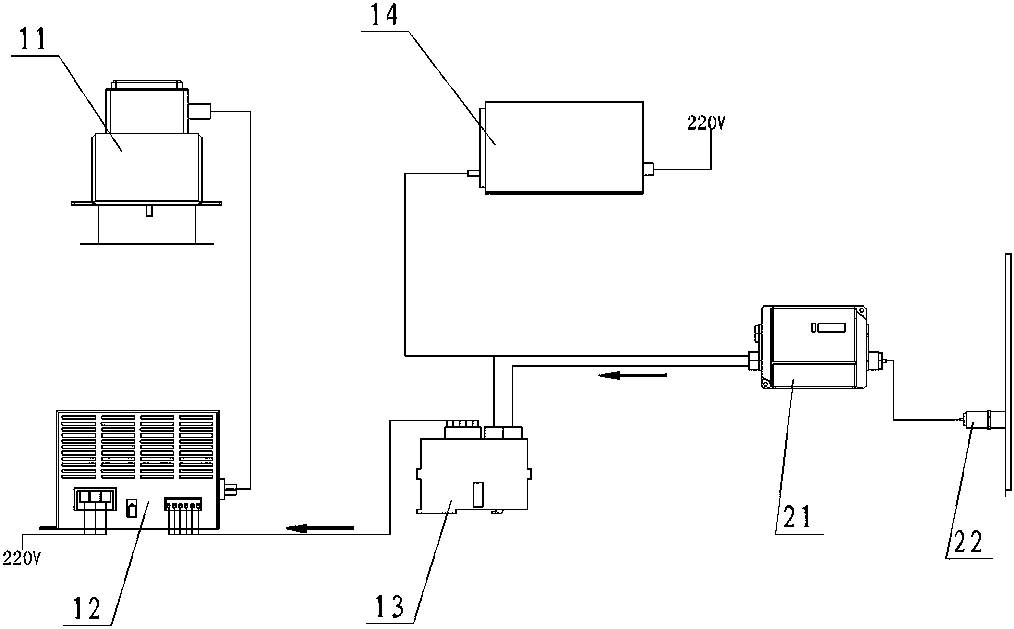
[0013] Such as figure 1 , figure 2 and image 3 As shown, a constant temperature control device for a microwave synthesizer includes a microwave control system 1 , a temperature monitoring system 2 , and a rotation drive system 3 .

[0014] Described microwave control system 1 comprises microwave launcher 11, microwave transmission controller 12, PLC controller 13, DC 24V power supply 14; Described temperature monitoring system 2 comprises infrared temperature detection controller 21, infrared temperature detection probe 22; The rotary drive system 3 includes a servo motor driver 31 , a servo motor 32 , a rotating platform 33 , a main shaft 34 , a main disk 35 , and a reactor 36 . The microwave launch controller 12 is connected with the microwave launcher 11 through an output data line, and the microwave launch controller 12 is externally connected to 220V mains; the control signal line of the PLC controller 13 is connected with the microwave launch controller 12, and the ...


PUM


Abstract

The invention discloses a constant temperature control device of a microwave synthesizer and relates to the field of chemical synthesis equipment. The constant temperature control device comprises a microwave control system, a temperature monitoring system and a rotation driving system. The microwave control system comprises a microwave emitter, a microwave emission controller, a PLC controller and a DC 24V power supply. The temperature monitoring system comprises an infrared temperature detection probe and an infrared temperature detection controller. The rotation driving system comprises a servo motor driver, a servo motor, a rotation platform, a main shaft, a main disk and a reactor. Equalization of temperature in the reactor is ensured through real-time feedback of data; and the constant temperature control device can carry out multiple groups of experiment reactions in the reactor, thereby greatly improving reaction efficiency, and improving reaction effect.

Description

technical field [0001] The invention relates to the field of chemical synthesis equipment, in particular to a constant temperature control device of a microwave synthesizer. Background technique [0002] Now microwave technology has been used in all aspects of life, such as household microwave ovens, microwave reaction equipment is also widely used in scientific research laboratories. The microwave equipment currently used for scientific research is a traditional standing wave single-mode system, which is characterized by single-channel, one-way, high-density coupling, but the diameter of the single-mode energy interface is small, and the volume of the cavity is limited, and only 10-15ml can be placed in it. Another disadvantage of the container is that the single-mode power is limited by the cavity. Due to the high density and small body, it is easy to produce instantaneous leakage and excessive thermal coupling to damage the reactants, resulting in research failure. Chemi...

Claims


Application Information

Patent Timeline
Patent Type & Authority Applications(China)
IPC IPC(8): H05B6/64H05B6/68B01J19/12
CPCB01J19/126H05B6/6455H05B6/68
Inventor 张殿甫孙振朱玮贺笑笑
Owner 南京谱瑞生物科技有限公司
Learn More