
Ceramic tile printing machine

A technology of printers and ceramic tiles, applied in typewriters, printing, etc., can solve problems such as unsatisfactory printing effects, and achieve simple structure and good printing effects

Inactive Publication Date: 2018-02-27
HEFEI AIRWREN AUTOMATIC EQUIP CO LTD
View PDF6 Cites 1 Cited by
  • Summary
  • Abstract
  • Description
  • Claims
  • Application Information

AI Technical Summary

Problems solved by technology

[0003] The printing effect of existing ceramic tile printers is not ideal enough and needs to be further improved

Method used


Image

  • Ceramic tile printing machine
  • Ceramic tile printing machine
  • Ceramic tile printing machine

Examples


Embodiment Construction

[0025] It should be noted that, in the case of no conflict, the embodiments in the present application and the features in the embodiments can be combined with each other; the present invention will be described in detail below with reference to the accompanying drawings and in combination with the embodiments.

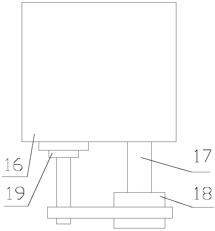
[0026] refer to figure 1 , 2 , 3:

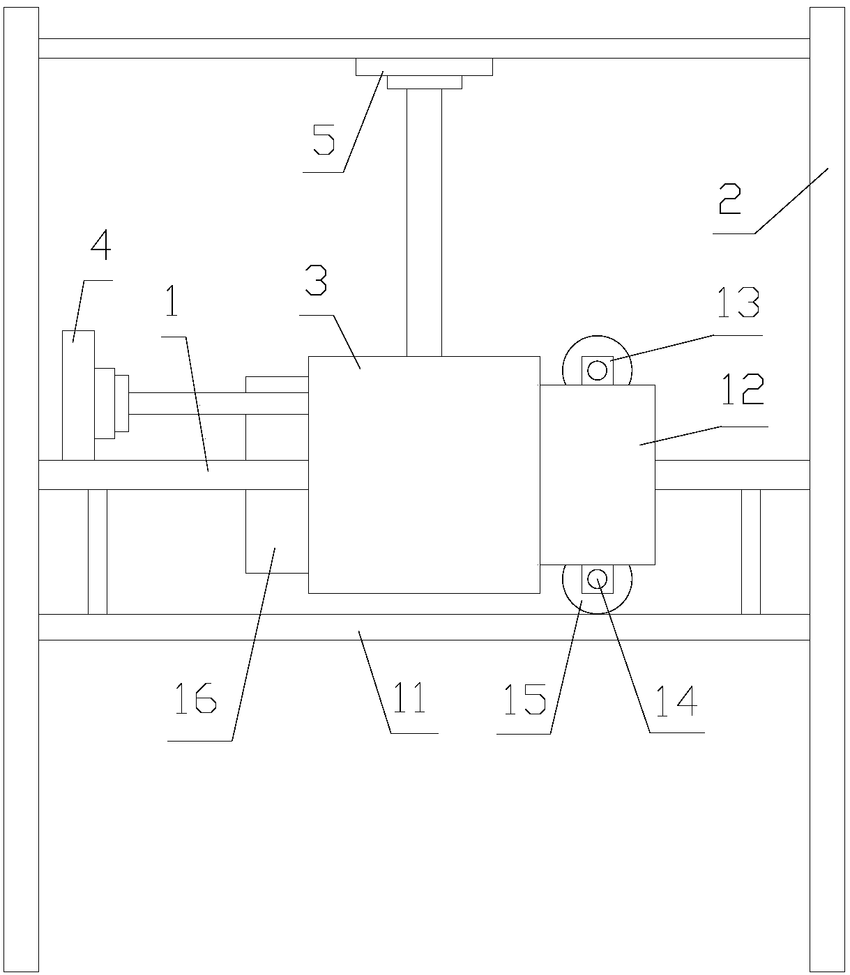
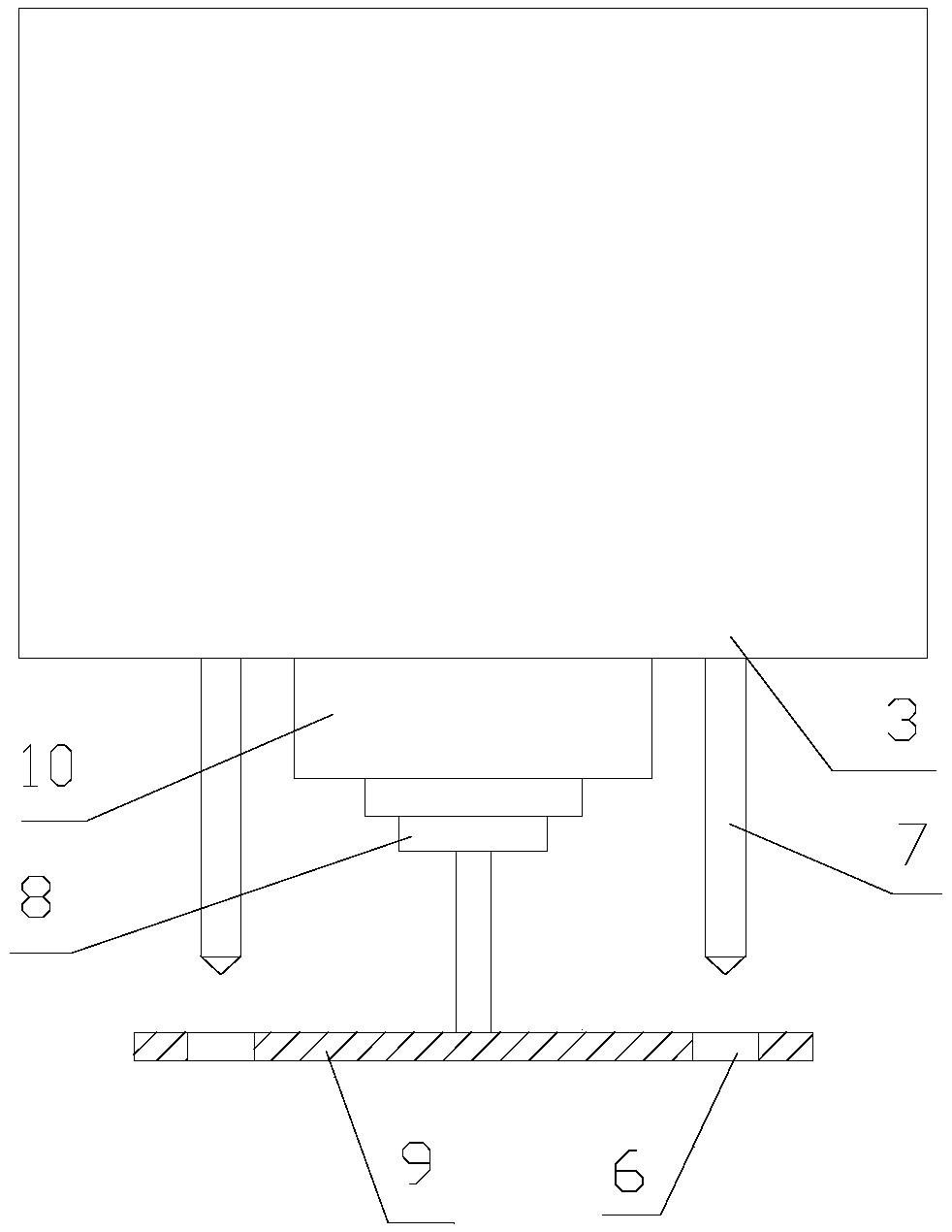
[0027] A tile printer proposed by the present invention includes a first guide rail 1, a second guide rail 2, an ink cartridge assembly 3, a first power unit 4, a second power unit 5, a plurality of nozzles 7, an execution unit 8, a baffle 9, a control device 10.

[0028] The first guide rail 1 is movably mounted on the second guide rail 2 , and the length direction of the first guide rail 1 is perpendicular or oblique to the length direction of the second guide rail 2 .

[0029] The ink cartridge assembly 3 is movably connected with the first guide rail 1; the first power unit 4 is used to drive the ink cartridge assembly 3 to m...


PUM


Abstract

The invention discloses a ceramic tile printing machine. The ceramic tile printing machine comprises a first guide rail, a second guide rail, an ink box assembly, a first power unit, a second power unit, a plurality of sprayers, an execution unit, a baffle and a controller. The first guide rail is movably arranged on the second guide rail. The length direction of the first guide rail is perpendicular to or obliquely intersects with the length direction of the second guide rail. The ink box assembly is movably connected with the first guide rail. The first power unit is used for driving the inkbox assembly to move along the first guide rail. The second power unit is used for driving the first guide rail to move along the second guide rail. The multiple sprayers are sequentially distributedand communicate with the ink box assembly. The baffle is provided with a plurality of through holes, and the multiple through holes correspond to the multiple sprayers in a one-to-one manner. The execution unit is used for driving the baffle to move so that the through holes can get in or disengage from the area below the sprayers. The ink box assembly and the execution unit are both in communication connection with the controller. The ceramic tile printing machine is good in ceramic tile printing effect.

Description

technical field [0001] The invention relates to the technical field of industrial printing, in particular to a ceramic tile printer. Background technique [0002] Ceramic tile printers can be applied to full-color printing of flat, curved or cylindrical objects of any material. Its subversive digital printing concept has brought a new trend to the printing industry, sweeping the entire industry unstoppably, and greatly benefiting customers. Reduce production costs, improve production efficiency and create good conditions to replace screen printing, pad printing, transfer printing equipment, no need for plate making, no need for color registration, and produce higher printing quality than traditional methods. The machine is easy to operate and stable in performance. Industry mass production requirements. [0003] The printing effect of existing ceramic tile printers is not ideal enough, and needs to be further improved. Contents of the invention [0004] In order to solve...

Claims


Application Information

Patent Timeline
IPC IPC(8): B41J3/407
CPCB41J3/407
Inventor 龙梅
Owner HEFEI AIRWREN AUTOMATIC EQUIP CO LTD
Learn More