
Magnetically-conductive half ring electroplating device

An electroplating device and magnetic conduction technology, applied in the electrolysis process, electrolysis components, etc., can solve the problems of poor plating quality on the surface of the winding position, increased production costs, and low electroplating efficiency, so as to improve electroplating efficiency, reduce labor costs, and operate simple effect

Active Publication Date: 2018-02-27
上海第一机床厂有限公司
View PDF5 Cites 0 Cited by
  • Summary
  • Abstract
  • Description
  • Claims
  • Application Information

AI Technical Summary

Problems solved by technology

Because the electroplating solution at the position where the iron wire is wound on the surface cannot fully contact the surface of the part, after the electroplating is completed, the electroplating quality on the surface of the wound position is not good, and the electroplating efficiency is low, which increases the production cost and the production cycle is longer

Method used


Image

  • Magnetically-conductive half ring electroplating device
  • Magnetically-conductive half ring electroplating device
  • Magnetically-conductive half ring electroplating device

Examples


Embodiment Construction

[0036] The specific implementation of the magnetic semi-ring electroplating device of the present invention will be described in detail below in conjunction with the accompanying drawings.

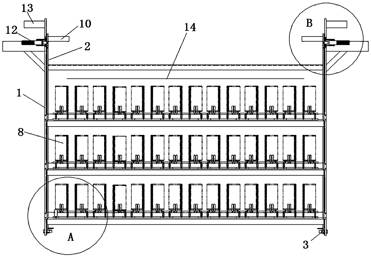
[0037] See attached figure 1 , the magnetic semi-ring electroplating device includes a large bracket 1 and a small bracket 2, the large bracket 1 and the small bracket 2 are rectangular structures, the small bracket 2 can be placed inside the large bracket 1, and a support seat 3 is set on the large bracket 1, and the small bracket 2 The bracket 2 is arranged in the large bracket 1 through the support seat 3, and the support seat 3 includes an angle steel arranged on the inner side of the bottom of the large bracket 1, and the angle steel is located on opposite sides of the short side of the large bracket 1.

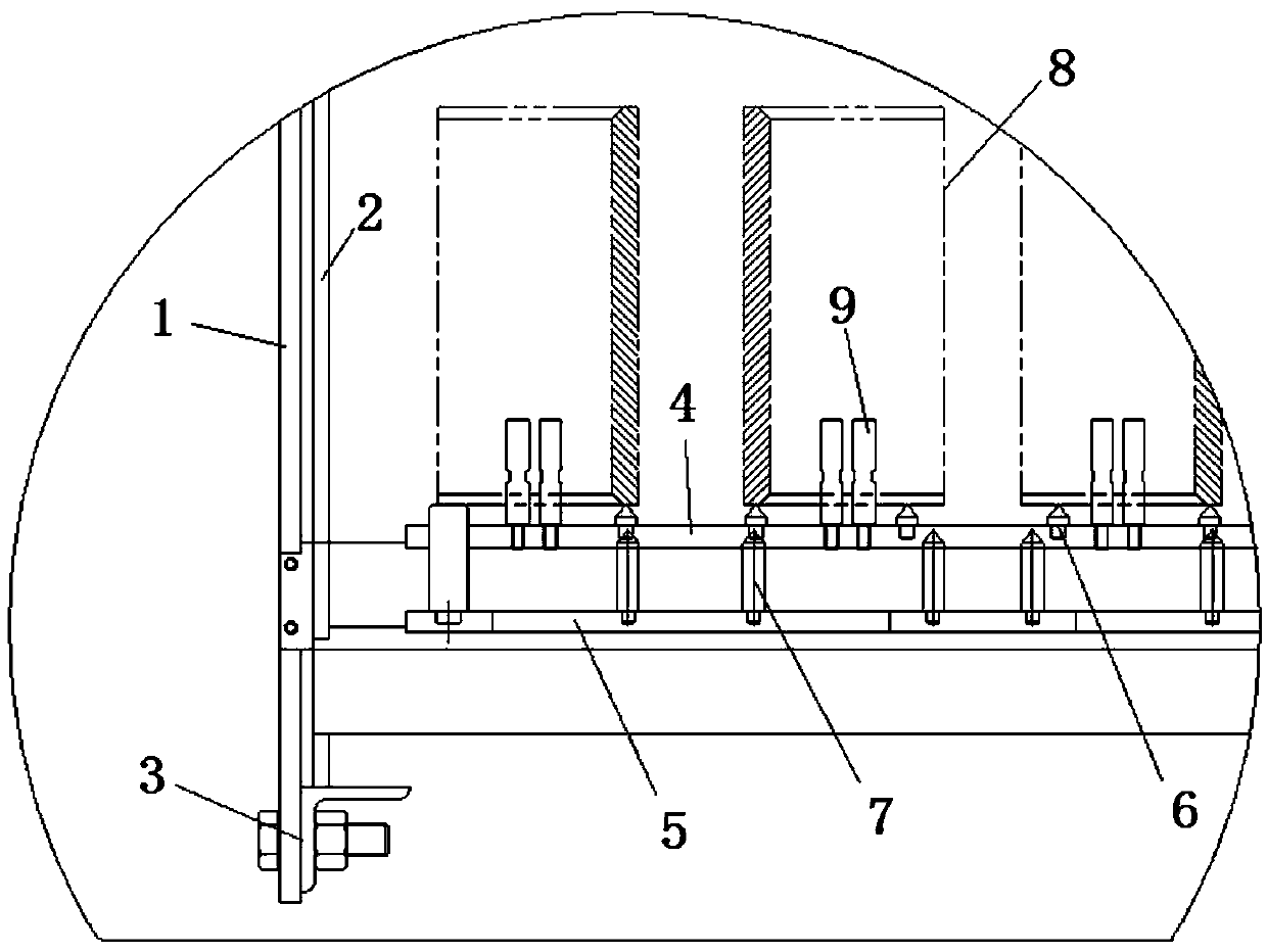
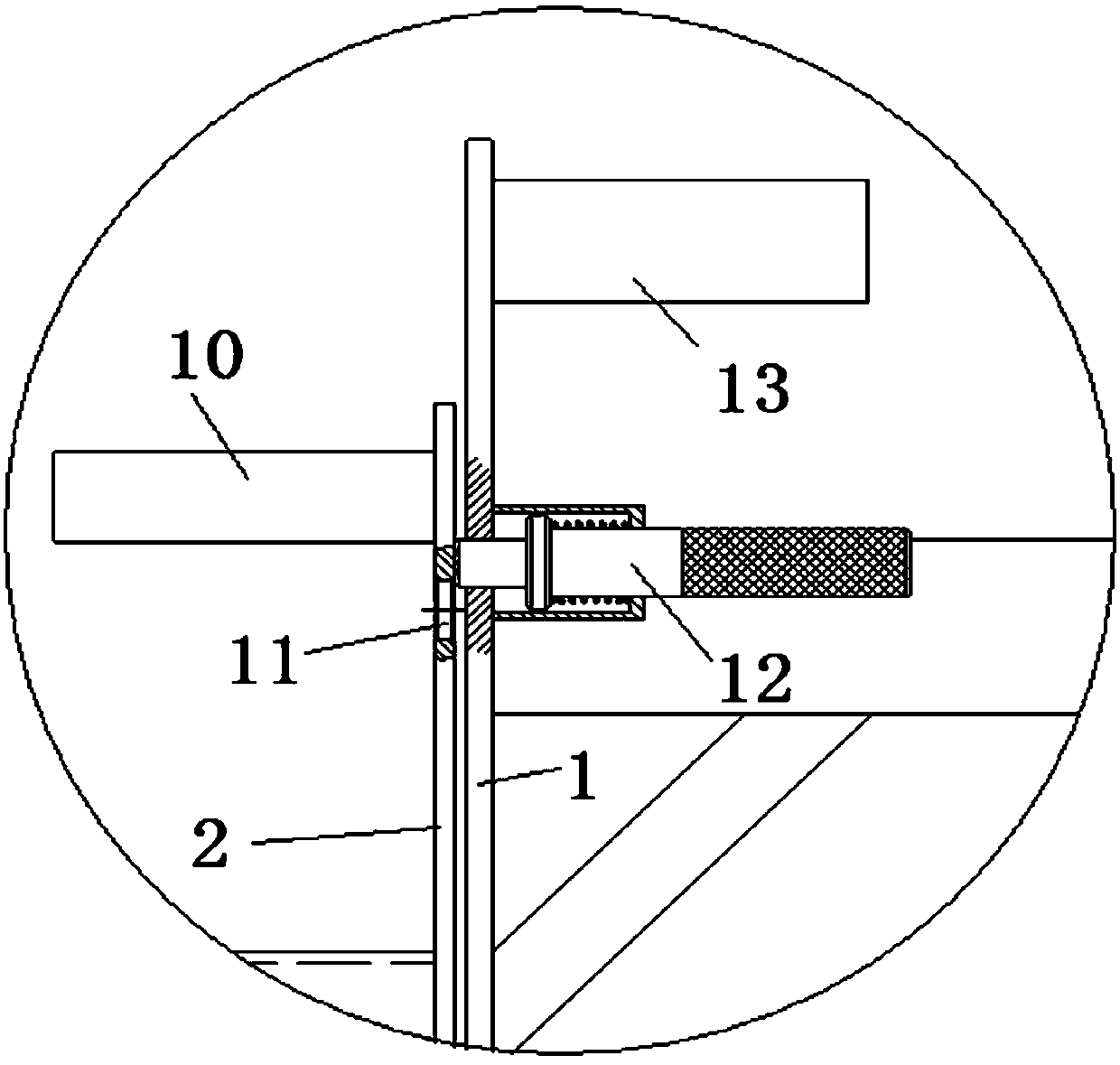
[0038] See attached Figures 1 to 4 , the first support bar 4 is set on the large support 1, the second support bar 5 is set on the small support 2, the second support bar 5 is loca...


PUM

PropertyMeasurementUnit
thicknessaaaaaaaaaa
thicknessaaaaaaaaaa

Abstract

The invention belongs to the technical field of nuclear reactor internal part machining production, and discloses a magnetically-conductive half ring electroplating device. The magnetically-conductivehalf ring electroplating device comprises a large bracket and a small bracket, the small bracket is arranged in the large bracket through supporting bases, a first supporting bar is arranged on the large bracket, a second supporting bar is arranged on the small bracket, each electroplating supporting assembly arranged on the first supporting bar and the second supporting bar comprises a pluralityof short supports arranged on the first supporting bar and a plurality of long supports arranged on the second supporting bar, the short supports and the long supports are arranged in a staggered mode, and the long supports are located under the short supports; and lifting assemblies are arranged over the small bracket and used for lifting the small bracket to the certain height and fixing the small bracket, wherein the lifting height is located between first distance and second distance. According to the magnetically-conductive half ring electroplating device, batched electroplating is achieved, and it is guaranteed that the quality and the thickness of all surface nickel-plated layers of magnetically-conductive half rings meet the requirements.

Description

technical field [0001] The invention belongs to the technical field of processing and production of nuclear reactor internal parts, in particular to a magnetic half-ring electroplating device. Background technique [0002] The magnetic semi-ring part in the PWR control rod drive mechanism is an important part in the PWR. The material of the magnetic semi-ring is 10#. In order to prevent the surface oxidation and corrosion of the magnetic semi-ring, it is necessary to All surfaces are nickel-plated, and the thickness of the nickel-plated layer is 0.03mm to 0.08mm. [0003] In the existing electroplating process, a thin iron wire is used to wrap the magnetically conductive half-ring, and then the magnetically conductive half-ring is immersed in an electroplating solution for electroplating. Because the electroplating solution at the position where the iron wire is wound on the surface cannot fully contact the surface of the part, after the electroplating is completed, the ele...

Claims


Application Information

Patent Timeline
Patent Type & Authority Applications(China)
IPC IPC(8): C25D17/06
CPCC25D17/06Y02P10/20
Inventor 杨平汉张超群钱翊郑亮刘海涛
Owner 上海第一机床厂有限公司
Learn More