Comprehensive protecting system of power communication machine room

A technology for power communication and protection systems, applied to circuits, electrical components, corona discharge devices, etc., can solve problems such as the difficulty of dispatching personnel on duty or manual inspection, interference with the stability of communication signal transmission, and affecting the safe use of computer rooms, etc., to achieve Good protection performance, improved bird repellent performance, and the effect of resisting lightning strikes

Inactive Publication Date: 2018-03-02
ZHONGSHAN HOUYUAN ELECTRONICS TECH CO LTD
View PDF0 Cites 1 Cited by
  • Summary
  • Abstract
  • Description
  • Claims
  • Application Information

AI Technical Summary

Problems solved by technology

In addition, after the implementation of the optical cable community, the number of access points in the community has increased greatly, and the communication room has become an important part of the telecommunications network. The power and environmental equipment in the room must provide a normal operating environment for the communication system at all times. If the equipment fails, it will affect the operation of the communication network, and the consequences will be disastrous
[0003] The communication machine rooms in the prior art are usually built in the wild and there are a large n

Method used


Image

  • Comprehensive protecting system of power communication machine room
  • Comprehensive protecting system of power communication machine room
  • Comprehensive protecting system of power communication machine room

Examples


Example Embodiment

[0017] In order to make the technical means, creative features, objectives and effects of the present invention easy to understand, the present invention will be further explained below in conjunction with specific embodiments.
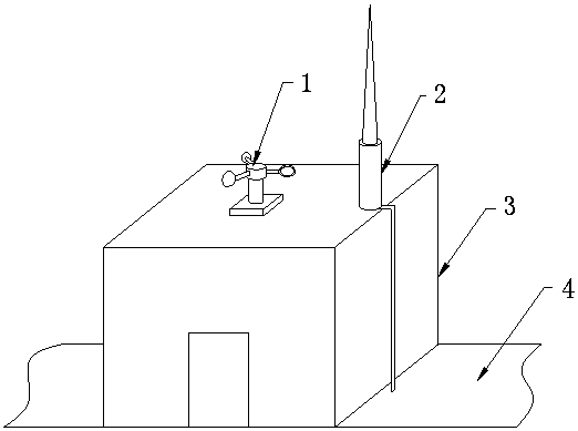
[0018] See Figure 1-Figure 3 , The present invention provides a technical solution: a comprehensive protection system for a power communication machine room, including a ground 4, a machine room main body 3, a bird repellent mechanism 1, and a lightning protection mechanism 2. The machine room main body 3 is installed on the upper end surface of the ground 4.
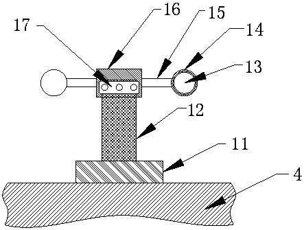
[0019] The bird repellent mechanism 1 is arranged on the upper end surface of the main body 3 of the machine room. The bird repellent mechanism 1 is composed of a fixed flange 11, a support column 12, a reflector 13, a fan blade seat 14, a connecting rod 15, a housing 16 and a bearing 17. The fixed flange 11 is installed on the upper end of the main body 3 of the machine room, the support column 12...


PUM


Abstract

The invention provides a comprehensive protection system for a power communication machine room, which includes the ground, the main body of the machine room, a fixed flange, a support column, a reflector, a fan blade seat, a connecting rod, a casing, a bearing, a lightning receptor, an electronic discharger, a lead wire, and a grounding The support column is assembled on the upper end surface of the fixed flange, the housing is installed on the upper end of the support column, the housing is connected to the support column through a bearing, and the fan blade seat is connected to the side of the housing through a connecting rod , the reflector is installed in the fan blade seat, the electronic discharger is installed on the upper end surface of the main body of the machine room, the lightning receptor is assembled on the upper end surface of the electronic discharger, the upper end of the lead is connected to the electronic discharger, the The lower end of the lead wire is connected to the grounding wire, the grounding wire is installed at the lower end of the ground, the lower end of the grounding wire is connected to the power grid, and the power grid is assembled at the lower end of the ground. The invention has reasonable structure, good protection performance, and effectively ensures the stability and safety of the operation of the communication room. Good performance and high reliability.

Description

technical field [0001] The invention relates to a comprehensive protection system for a power communication machine room, which belongs to the field of power communication equipment. Background technique [0002] With the rapid development of the telecommunication industry, the number of telecommunication users has risen sharply. In addition, after the implementation of the optical cable community, the number of access points in the community has increased greatly, and the communication room has become an important part of the telecommunications network. The power and environmental equipment in the room must provide a normal operating environment for the communication system at all times. If the equipment fails, it will affect the operation of the communication network, and the consequences will be disastrous. [0003] The communication machine rooms in the prior art are usually built in the wild and there are a large number of them. It is very difficult to send people on d...

Claims


Application Information

Patent Timeline
IPC IPC(8): A01M29/08A01M29/32H01T19/04H05K7/20
CPCA01M29/08A01M29/32H01T19/04H05K7/20136
Inventor 胡录录陈维安杨双录
Owner ZHONGSHAN HOUYUAN ELECTRONICS TECH CO LTD
Why Eureka
Try Eureka