Punch with feeding device

A technology of feeding device and punching machine, applied in the direction of operating device, forging/pressing/hammer device, forging/pressing/hammering machinery, etc., can solve the problems of physical injury of workers, low precision of workpiece, low processing efficiency, etc., and achieve increase Weight, stable operation, life-saving effects

Inactive Publication Date: 2018-03-02
茹子俊
View PDF0 Cites 7 Cited by
  • Summary
  • Abstract
  • Description
  • Claims
  • Application Information

AI Technical Summary

Problems solved by technology

[0003] When the existing stamping machine processes the workpiece, the workers generally send the workpiece to the mold for processing. This method is dangerous, and it is easy to cause harm to the worker's body. The processing efficiency is also relatively low, and the precision of the processed workpiece is also relatively low.

Method used


Image

  • Punch with feeding device
  • Punch with feeding device
  • Punch with feeding device

Examples


Embodiment Construction

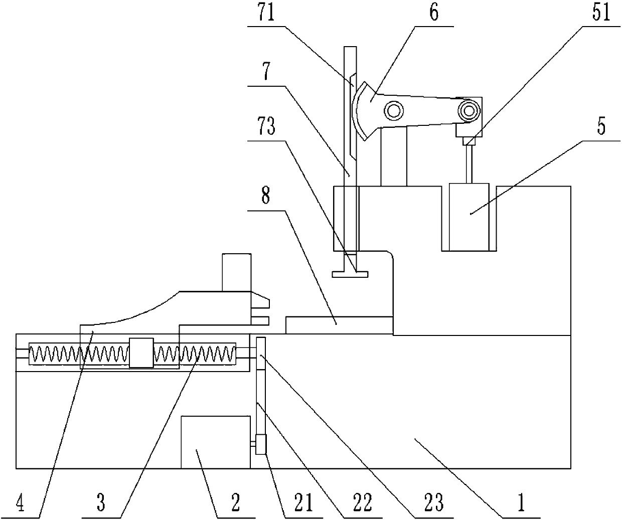
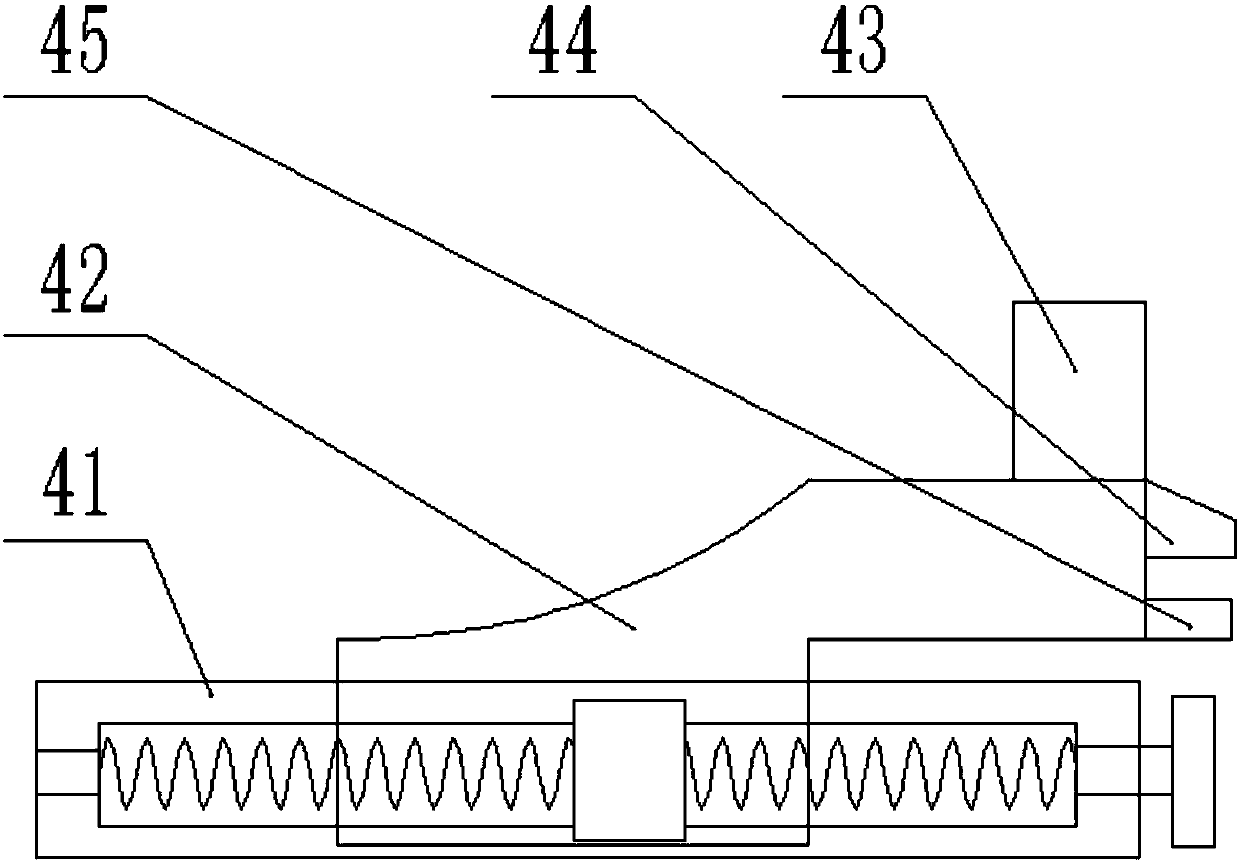
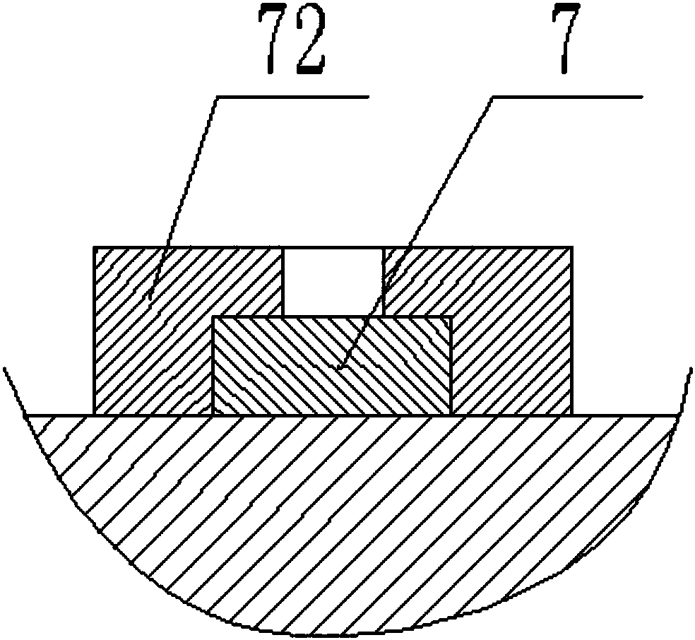
[0013] Such as Figure 1-Figure 3 As shown, a punching machine with a feeding device mainly includes a frame 1, a cylinder 5 and a workbench 7, the left end of the bottom of the frame 1 is provided with a driving device, and the driving device includes a driving motor 2, a first pulley 21 , the second pulley 23 and the belt 22; the driving motor 2 drives and connects the first pulley 21, the first pulley 21 drives and connects the second pulley 23 through the belt 22, and the second pulley 23 drives and connects the ball screw mechanism 3; the upper left side of the frame 1 is provided with a sliding device 4, the sliding device 4 includes a guide rail 41 and a slider 42, the ball screw mechanism 3 is located inside the guide rail 41, and the ball screw mechanism 3 drives and connects the slider 42, the sliding The top of the right end of the block 42 is fixedly provided with a clamping cylinder 43, the clamping cylinder 43 is driven and connected with an upper clamping block ...


PUM


Abstract

A stamping machine with a feeding device, mainly including a frame, a cylinder and a workbench, the left end of the bottom of the frame is provided with a driving device, the driving device includes a driving motor, a first pulley, a second pulley and a belt; The drive motor is connected to the first pulley, the first pulley is connected to the second pulley through the belt drive, and the second pulley is connected to the ball screw mechanism by driving; the upper left side of the frame is provided with a sliding device, and the sliding device includes a guide rail And the slider, the ball screw mechanism is located inside the guide rail, and the ball screw mechanism drives the connecting slider, and the top of the right end of the slider is fixed with a clamping cylinder; the driving motor drives the ball screw mechanism to rotate to realize the feeding function. The clamping cylinder is used to realize the clamping and loosening of the workpiece, the workpiece is clamped first and then transferred, the operation is stable, the efficiency is high, and the cost is low.

Description

technical field [0001] The invention relates to a stamping machine, in particular to a stamping machine with a feeding device. Background technique [0002] In national production, the stamping process has the advantages of saving materials and energy, high efficiency, low technical requirements for operators, and products that cannot be achieved by mechanical processing through various mold applications. Its use is more and more extensive. The stamping machine is a kind of forging machinery, and its main function is the metal processing industry. The products are widely used in aviation, light industry, metallurgy, chemical industry, construction, shipbuilding, automobile, electric power, electrical appliances, decoration and other industries to provide the required special machinery and complete sets of equipment. [0003] When the existing stamping machine processes the workpiece, the workers generally send the workpiece to the mold for processing. This method is danger...

Claims


Application Information

Patent Timeline
Patent Type & Authority Applications(China)
IPC IPC(8): B21J13/10B21K27/00
CPCB21J13/10B21K27/00
Inventor 茹子俊
Owner 茹子俊
Why Eureka
Try Eureka