Sea surface wind field inversion method and device
A wind field inversion and sea surface technology, which is applied in the directions of measurement devices, radio wave reflection/re-radiation, and re-radiation, can solve the problem of large error in wind speed inversion
- Summary
- Abstract
- Description
- Claims
- Application Information
AI Technical Summary
Problems solved by technology
Method used
Image
Examples
Embodiment 1
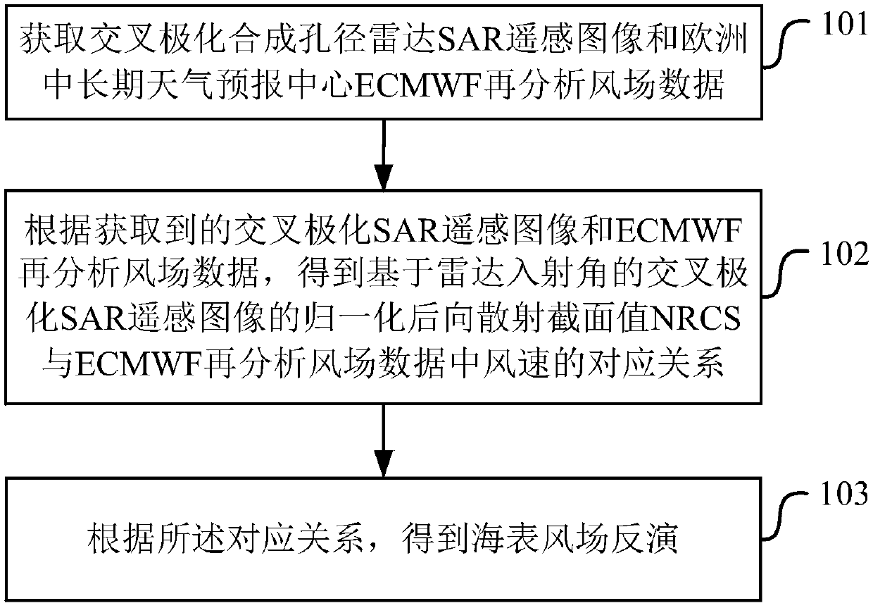
[0048] figure 1 Shows the schematic diagram of the method for sea surface wind field inversion in Embodiment 1 of the present application, as figure 1 shown, including:
[0049] Step 101: Obtain cross-polarization synthetic aperture radar SAR remote sensing images and ECMWF reanalysis wind field data.
[0050] Step 102: According to the obtained cross-polarization SAR remote sensing image and ECMWF reanalysis wind field data, obtain the normalized backscattering cross-section value NRCS and ECMWF reanalysis wind field data of the cross-polarization SAR remote sensing image based on the radar incident angle Corresponding relationship of wind speed.
[0051] Step 103: Obtain sea surface wind field inversion according to the corresponding relationship.
[0052] In implementation, the NRCS based on the radar incidence angle interval is obtained by radiometrically calibrating the cross-polarization SAR remote sensing images, which include VH polarization and HV polarization SAR ...
Embodiment 2
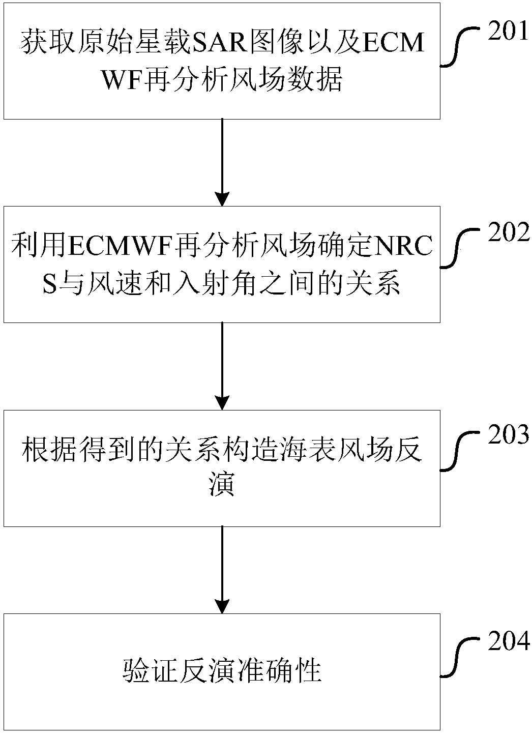
[0064] figure 2 Shows the flow chart of the method for sea surface wind field inversion in Embodiment 2 of the present application, as figure 2 as shown,
[0065] The present invention realizes sea surface wind field inversion from low wind speed to high wind speed based on Sentinel-1 SAR cross polarization, that is, VH polarization and HV polarization, such as figure 2 As shown, the method includes:
[0066] 201: Obtain original spaceborne SAR images and ECMWF reanalysis wind field data.
[0067] Collect 328 Sentinel-1GRD SM mode SAR remote sensing images, each image has a single pixel width of 10 meters, and there are very few images caused by other ocean phenomena such as upwelling, rainfall or oil slicks in the collected SAR remote sensing images out of shape. At the same time, ECMWF reanalysis wind field data with a time interval of 6 hours and a resolution of 0.125°×0.125°, or about 12.5km×12.5km, were collected. When matching the ECMWF reanalysis wind field data...
Embodiment 3
[0096] Figure 6 Shows the device structure diagram of the inversion of the sea surface wind field in the third embodiment of the present application, as Figure 6 As shown, the device may include an acquisition module 601 , a matching module 602 , an inversion module 603 and a verification module 604 .
[0097] The acquiring module 601 is configured to acquire cross-polarization synthetic aperture radar SAR remote sensing images and ECMWF reanalysis wind field data, and the cross-polarization SAR remote sensing images include NDBC buoys of the US National Aids to Navigation Data Center.
[0098] The matching module 602 is used to reanalyze the wind field data according to the obtained cross-polarization SAR remote sensing image and ECMWF, and obtain the normalized backscattering cross-section value NRCS and ECMWF reanalysis of the cross-polarization SAR remote sensing image based on the radar incident angle Correspondence of wind speed in wind field data.
[0099] The inver...
PUM
 Abstract
Description
Claims
Application Information
 - R&D
- Intellectual Property
- Life Sciences
- Materials
- Tech Scout
- Unparalleled Data Quality
- Higher Quality Content
- 60% Fewer Hallucinations
Browse by: Latest US Patents, China's latest patents, Technical Efficacy Thesaurus, Application Domain, Technology Topic, Popular Technical Reports.
© 2025 PatSnap. All rights reserved.Legal|Privacy policy|Modern Slavery Act Transparency Statement|Sitemap|About US| Contact US: help@patsnap.com


