
Electroluminescent display panel and display device

An electroluminescent display and panel technology, which is applied in circuits, electrical components, electrical solid devices, etc.

Active Publication Date: 2018-03-02
WUHAN TIANMA MICRO ELECTRONICS CO LTD
View PDF8 Cites 19 Cited by
  • Summary
  • Abstract
  • Description
  • Claims
  • Application Information

AI Technical Summary

Problems solved by technology

[0003] Embodiments of the present invention provide an electroluminescence display panel and a display device, which are used to solve the problems existing in the prior art of how to realize the thin design and narrow frame design of the display

Method used


Image

  • Electroluminescent display panel and display device
  • Electroluminescent display panel and display device
  • Electroluminescent display panel and display device

Examples


Embodiment Construction

[0013] The specific implementation manners of an electroluminescent display panel and a display device provided by the embodiments of the present invention will be described in detail below with reference to the accompanying drawings. It should be noted that the described embodiments are only some of the embodiments of the present invention, but not all of the embodiments. Based on the embodiments of the present invention, all other embodiments obtained by persons of ordinary skill in the art without making creative efforts belong to the protection scope of the present invention.

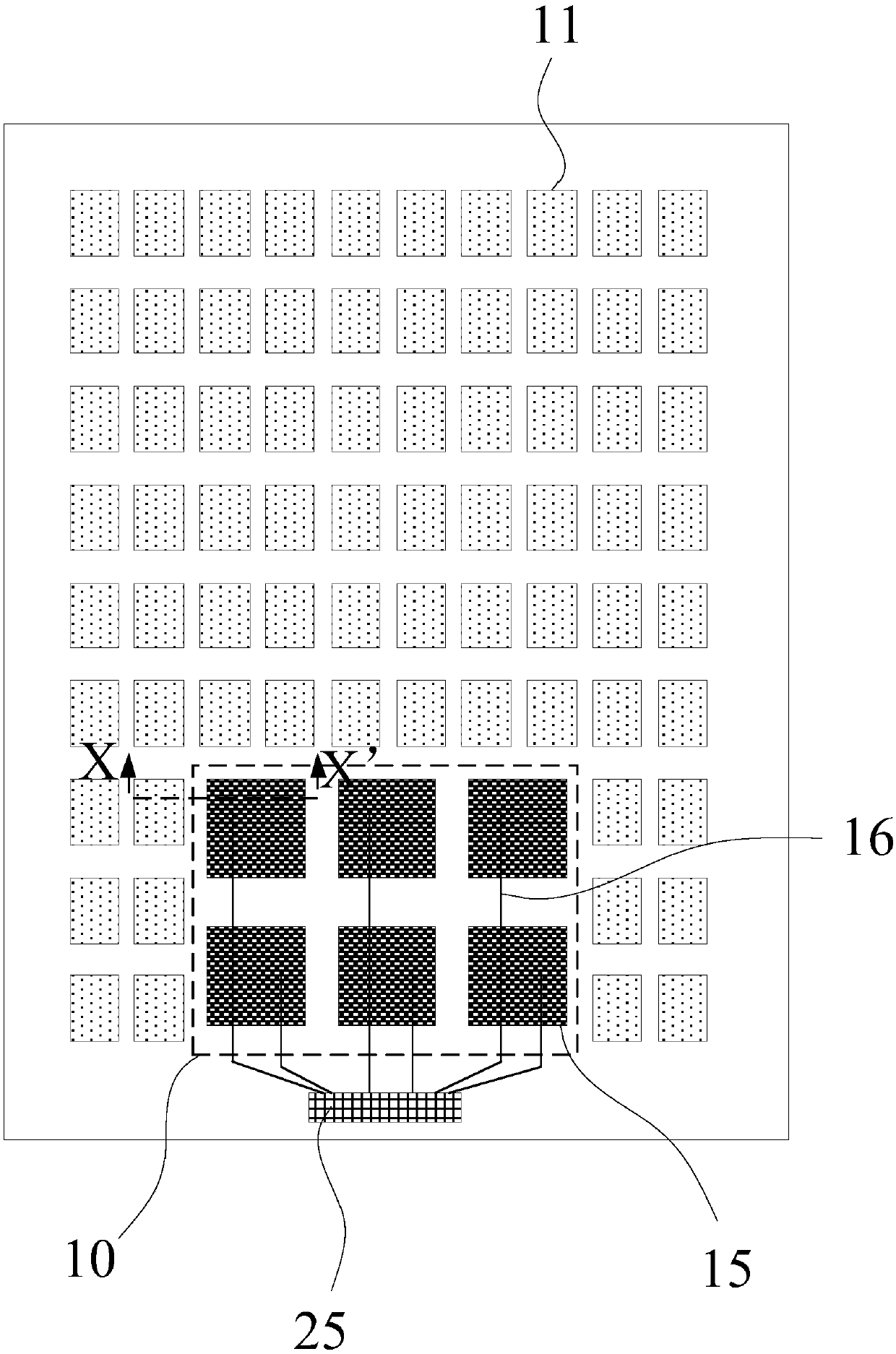
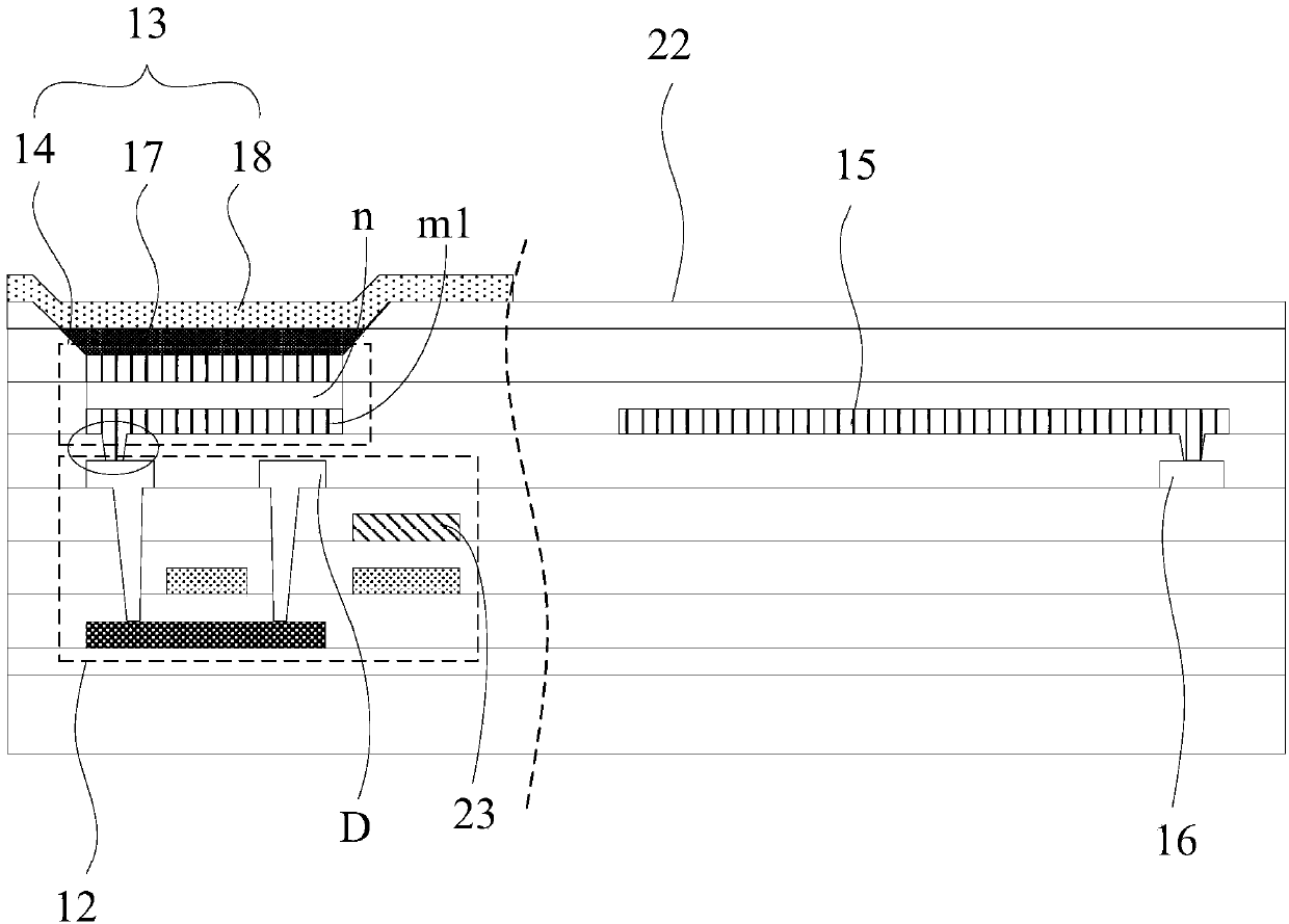
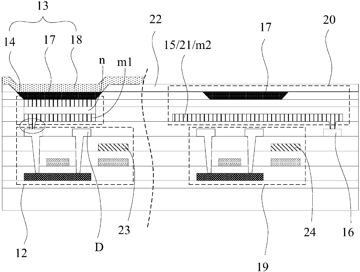
[0014] An embodiment of the present invention provides an electroluminescent display panel, such as Figure 1 to Figure 4 As shown, among them, figure 1 is a top view of an electroluminescent display panel, Figure 2 to Figure 4 respectively along the figure 1 The cross-sectional view of the dotted line X-X' shown in ; the electroluminescent display panel may include: a display area and a fingerp...


PUM


Abstract

The invention discloses an electroluminescent display panel and a display device. The electroluminescent display panel comprises a display area and a fingerprint recognition area. The display area comprises display pixel units. Each display pixel unit comprises a first pixel control circuit and a first light emitting unit. The first light emitting unit comprises a first anode. The fingerprint recognition area comprises multiple capacitive fingerprint recognition electrodes which are arranged in arrays and electrode wires which are arranged to be corresponding to and electrically connected withall the capacitive fingerprint recognition electrodes in a one-to-one way. The capacitive fingerprint recognition electrodes and the first anodes have the same material and are arranged on the same layer. The capacitive fingerprint recognition electrodes are arranged and the capacitive fingerprint recognition electrodes are enabled to be arranged in the electroluminescent display panel so that the thickness of the electroluminescent display panel can be reduced and the thinned design can be realized. Besides, the capacitive fingerprint recognition electrodes and the first anodes have the samematerial and are arranged on the same layer so that the manufacturing difficulty of the electroluminescent display panel can be effectively reduced and the manufacturing cost can be saved.

Description

technical field [0001] The invention relates to the field of display technology, in particular to an electroluminescent display panel and a display device. Background technique [0002] Organic Light Emitting Diode (OLED) display is a self-luminous display, and has the characteristics of thinness, high chromaticity, wide viewing angle and fast response speed, and has great development prospects in the field of display technology. In order to make the display have a fingerprint identification function, generally a fingerprint identification area is provided on the non-display area of ​​the display and on the display surface of the display or on the back of the display, and a fingerprint identification structure is usually provided in the fingerprint identification area; It is not conducive to the thin design of the display, and it is also not conducive to the design of the narrow frame of the display; based on this, how to realize the thin design and narrow frame design of th...

Claims


Application Information

Patent Timeline
Patent Type & Authority Applications(China)
IPC IPC(8): H01L27/32G06K9/00
CPCG06V40/1306H10K59/00H10K59/40H10K59/131
Inventor 马扬昭彭涛王永志李波
Owner WUHAN TIANMA MICRO ELECTRONICS CO LTD
Learn More