Wireless electric energy transmission system based on magnetic resonance coupling

A technology of wireless power transmission and magnetic resonance coupling, which is applied in current collectors, electric vehicles, electrical components, etc., can solve problems such as low efficiency of wireless power transmission and uneven distribution of the magnetic field at the receiving end

Inactive Publication Date: 2018-03-02
武汉广睿联科技有限公司
View PDF6 Cites 6 Cited by
  • Summary
  • Abstract
  • Description
  • Claims
  • Application Information

AI Technical Summary

Problems solved by technology

[0004] The purpose of the present invention is to overcome the shortcomings of the above-mentioned prior art and propose a magnetic resonance coupled wireless power transmission system based on a coil structure with a uniform magnetic field distribution. The problem of uneven distribution of the magnetic field at the receiving end is caused, and the auxiliary coil can be used to accept the magnetic flux leakage of the magnetic field around the main coil to solve the problem of low efficiency of wireless power transmission

Method used


Image

  • Wireless electric energy transmission system based on magnetic resonance coupling
  • Wireless electric energy transmission system based on magnetic resonance coupling
  • Wireless electric energy transmission system based on magnetic resonance coupling

Examples


Embodiment Construction

[0027] The present invention will be further described in detail below in conjunction with the accompanying drawings and specific embodiments.

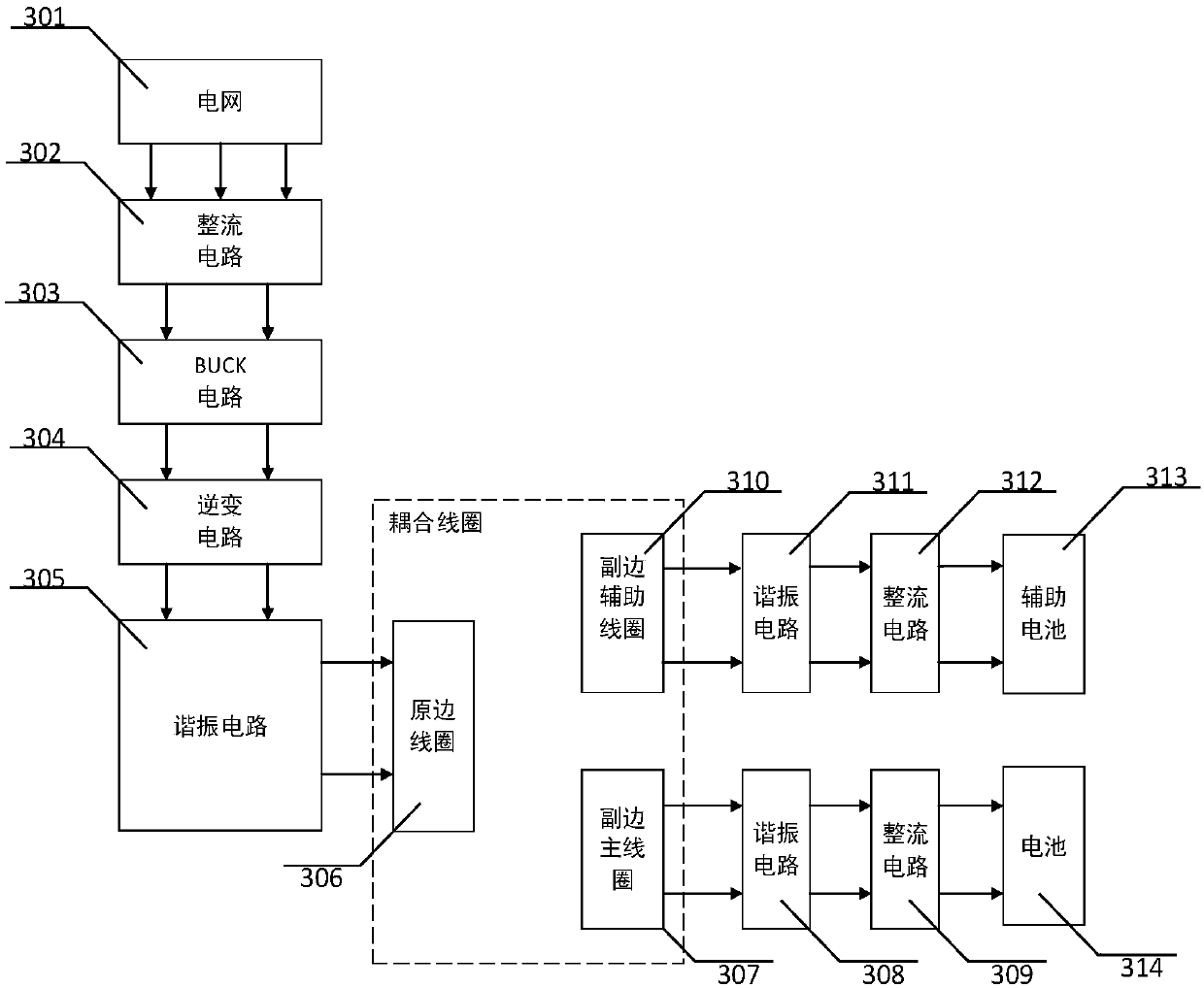
[0028] Such as figure 1 As shown, the wireless power transmission system based on magnetic resonance coupling of the present invention includes: power grid 301, rectifier circuit 302, BUCK circuit, inverter circuit 304, primary side resonant circuit 305, primary side coil 306, secondary side main coil 307, secondary side Main coil resonant circuit 308 , secondary main coil rectifier circuit 309 , secondary auxiliary coil 310 , secondary auxiliary coil resonant circuit 311 , secondary auxiliary coil rectifier circuit 312 , auxiliary battery module 313 , battery module 314 .

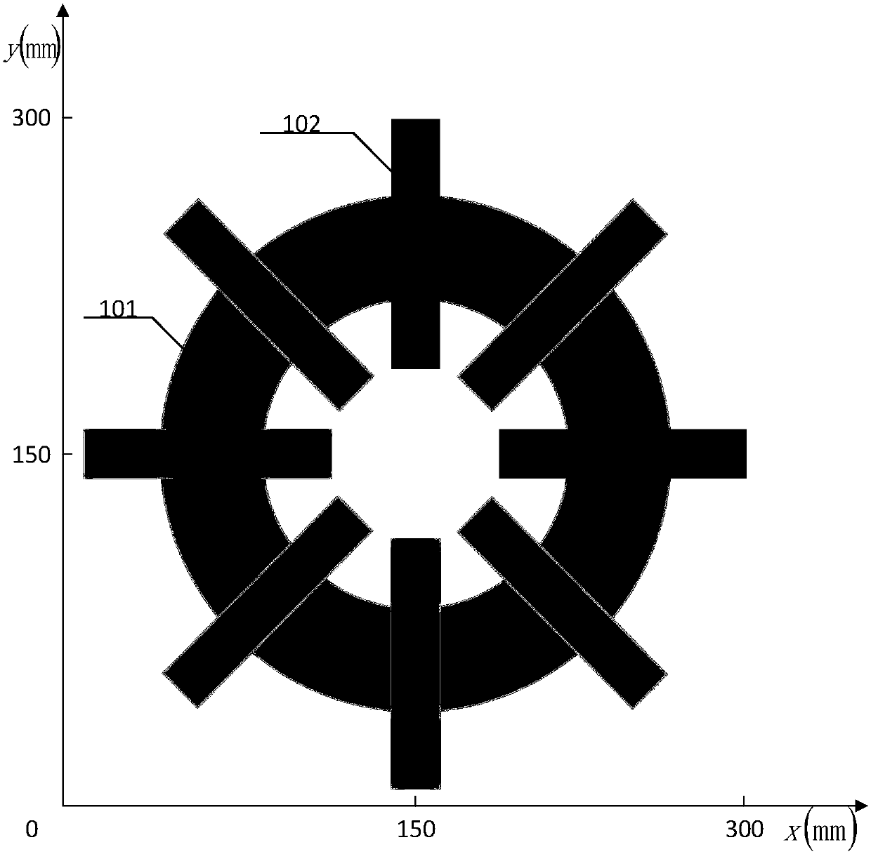
[0029] The core of the wireless power transmission system of the present invention is that it also includes a power transmission module (primary side), and the structure of the power transmission module is as follows figure 2 As shown, it includes: a main coil 1...


PUM


Abstract

The invention relates to a coil structure of a wireless electric energy transmission system and especially relates to a wireless electric energy transmission system based on magnetic resonance coupling. A structure core is that magnetic field distribution of an electric energy receiving end is uniform and an auxiliary coil can receive a part of magnetic field which is scattered around a main coilso that losses can be reduced and partial overheating of a magnetic core can be restrained. In a structure of the whole wireless electric energy transmission system, losses of a coupling coil portionoccupy a large portion of losses of the whole system. By using the coil structure, the losses can be greatly reduced and transmission efficiency of wireless electric energy is increased.

Description

technical field [0001] The invention relates to a wireless power transmission system related to magnetic resonance for uniformly distributing a magnetic field, and belongs to the field of wireless power transmission. Background technique [0002] With the development of power electronics technology and the widespread use of new energy sources, electric vehicles have been widely popularized as a new type of pollution-free vehicles. However, the low power density and long charging time of electric vehicles restrict their further development and promotion. One of the most widely used charging methods at present is the wired charging method based on DC charging piles. These wires not only limit the charging range of the car, but also limit the convenience of using the car, which in turn creates hidden dangers in the safe use of electricity. Therefore, wireless charging technology has begun to attract attention in the field of electric vehicles. [0003] The mode and mechanism ...

Claims


Application Information

Patent Timeline
Patent Type & Authority Applications(China)
IPC IPC(8): H02J50/12H02J7/02
CPCH02J7/025H02J50/12
Inventor 张立炎龙汉平钱杭刘佳
Owner 武汉广睿联科技有限公司
Why Eureka
Try Eureka