Electric vehicle voltage automatic adjustment circuit

An electric vehicle, automatic adjustment technology, applied in the direction of adjusting electrical variables, control/regulating systems, electrical components, etc., can solve problems such as changes, and achieve the effect of ensuring changes

Active Publication Date: 2019-01-04
戴金燕
View PDF4 Cites 0 Cited by
  • Summary
  • Abstract
  • Description
  • Claims
  • Application Information

AI Technical Summary

Problems solved by technology

[0004] In view of the above situation, in order to overcome the defects of the prior art, the purpose of the present invention is to provide an electric vehicle voltage automatic adjustment circuit, which has the characteristics of ingenious design and humanized design, and effectively solves the problem of ensuring the output voltage of the power supply when the electric vehicle is running. Stability, but also to ensure the change of its power supply

Method used


Image

  • Electric vehicle voltage automatic adjustment circuit
  • Electric vehicle voltage automatic adjustment circuit

Examples


Embodiment 1

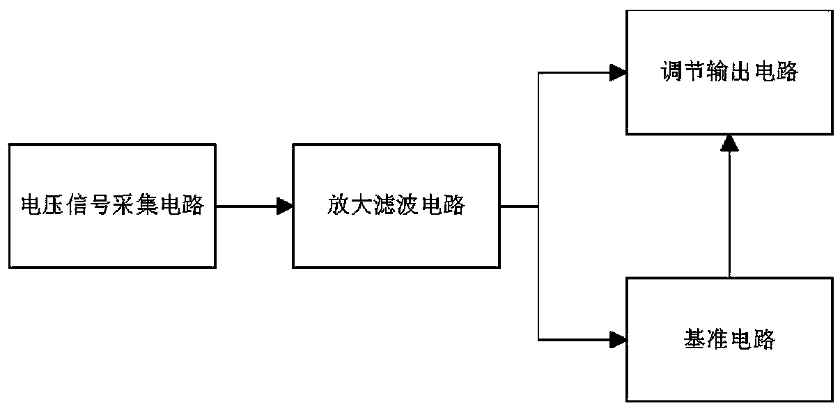
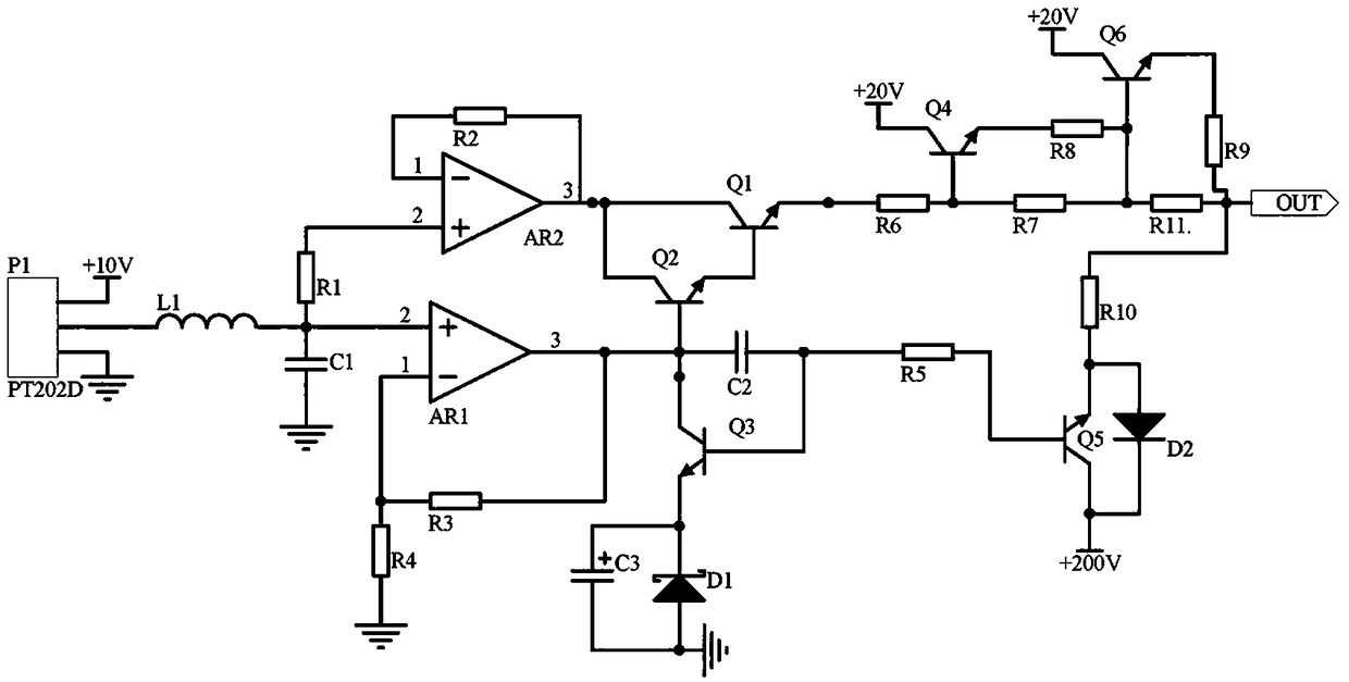
[0013] Embodiment 1, the electric vehicle voltage automatic adjustment circuit includes a voltage signal acquisition circuit, an amplification and filtering circuit, a reference circuit and an adjustment output circuit. The operational amplifiers AR1 and AR2 amplify the input signal of the voltage signal acquisition circuit, and use the triode Q1, Q2, capacitor C2 and triode Q3 to form a compound circuit for filtering. The signal output by the amplifying and filtering circuit is divided into two circuits, and one control reference circuit is the electric vehicle. The output port of the power supply provides the base voltage, and the other control and adjustment output circuit uses the principle of resistance voltage division to adjust the voltage to control the output voltage of the output port of the power supply;

[0014] Said amplification filter circuit utilizes operational amplifiers AR1 and AR2 to proportionally amplify the signal input by the voltage signal acquisition c...

Embodiment 2

[0015] Embodiment 2, on the basis of Embodiment 1, the voltage signal acquisition circuit selects the voltage transformer P1 model as PT202D to collect the output voltage of the power supply when the electric vehicle is running, and the power supply terminal of the voltage transformer P1 is connected to the power supply +10V. The ground terminal of the voltage transformer P1 is grounded, the output terminal of the voltage transformer P1 is connected to one end of the inductor L1, the other end of the inductor L1 is connected to one end of the capacitor C1, and the other end of the capacitor C1 is grounded.

Embodiment 3

[0016] Embodiment 3, on the basis of Embodiment 1, the reference circuit uses the triode Q5 to receive the signal output by the amplifying and filtering circuit. When the electric vehicle starts normally, the signal output by the amplifying and filtering circuit can turn on the triode Q5. At this time, the power supply +200V flows into the output port of the power supply after being divided by the transistor Q5 and the resistor R10, which is to supply power for electric vehicles. The voltage received by the output port of the power supply is +200V from the power supply plus +100V from the input voltage signal of the amplifying and filtering circuit, which is actually an electric vehicle. The power supply takes +200V as an example. When the electric vehicle changes speed during driving, the voltage signal collected by the voltage signal acquisition circuit becomes abnormally large, and the triode Q2 and Q1 are turned on. At this time, there are three levels of voltage regulation....


PUM


Abstract

The invention discloses a voltage automatic regulation circuit for an electric vehicle. The voltage automatic regulation circuit comprises a voltage signal acquisition circuit, an amplifying and filtering circuit, a reference circuit and a regulation output circuit. The voltage signal acquisition circuit acquires the output voltage of a power supply when an electric vehicle is running. The amplifying and filtering circuit amplifies signals input by the voltage signal acquisition circuit by using operational amplifiers AR1 and AR2. Triodes Q1 and Q2, a capacitor C2, and a triode Q3 are used toform a composite circuit for filtering. The signals output by the amplifying and filtering circuit are divided into two paths, one of which controls the reference circuit to provide a base voltage fora power output port of the electric vehicle, and the other of which controls the regulation output circuit to regulate the voltage by using the principle of resistance voltage-dividing and controls the output voltage of the power output port. The stability of the output voltage of the power supply is ensured, and the change of the power supply is also ensured.

Description

technical field [0001] The invention relates to the technical field of electric vehicles, in particular to an electric vehicle voltage automatic regulation circuit. Background technique [0002] Electric vehicles are a major trend in the development of future vehicles. Due to the gradual depletion of energy and the trend of environmental protection, traditional vehicles urgently need the introduction of new energy sources. Electric vehicles are environmentally friendly vehicles, but compared with traditional vehicles, their power output The problem has always been the weakness. The speed of electric vehicles changes in real time during driving, so the power supply of electric vehicles also needs to change in real time. The power output must not only ensure the stability of the output voltage of the power supply, but also ensure the change of its power supply. The current Electric vehicles can only stably adjust the voltage of the power supply within a certain range. Compared...

Claims


Application Information

Patent Timeline
Patent Type & Authority Patents(China)
IPC IPC(8): H02M3/156
CPCH02M3/156
Inventor 杨欣褚慧
Owner 戴金燕
Why Eureka
Try Eureka