
Electro-pneumatic brake control system

A braking control and pneumatic technology, applied in the direction of brakes, automatic starting devices, braking transmission devices, etc., can solve problems such as complex structures

Inactive Publication Date: 2020-06-23
KNORR-BREMSE SYST FUER NUTZFAHRZEUGE GMBH
View PDF1 Cites 0 Cited by
  • Summary
  • Abstract
  • Description
  • Claims
  • Application Information

AI Technical Summary

Problems solved by technology

A disadvantage of the solution proposed in this document is, inter alia, that a relatively complex construction is required for the purely mechanical or pneumatic triggering of the emptying of the spring accumulator brake cylinder

Method used


Image

  • Electro-pneumatic brake control system
  • Electro-pneumatic brake control system
  • Electro-pneumatic brake control system

Examples


Embodiment Construction

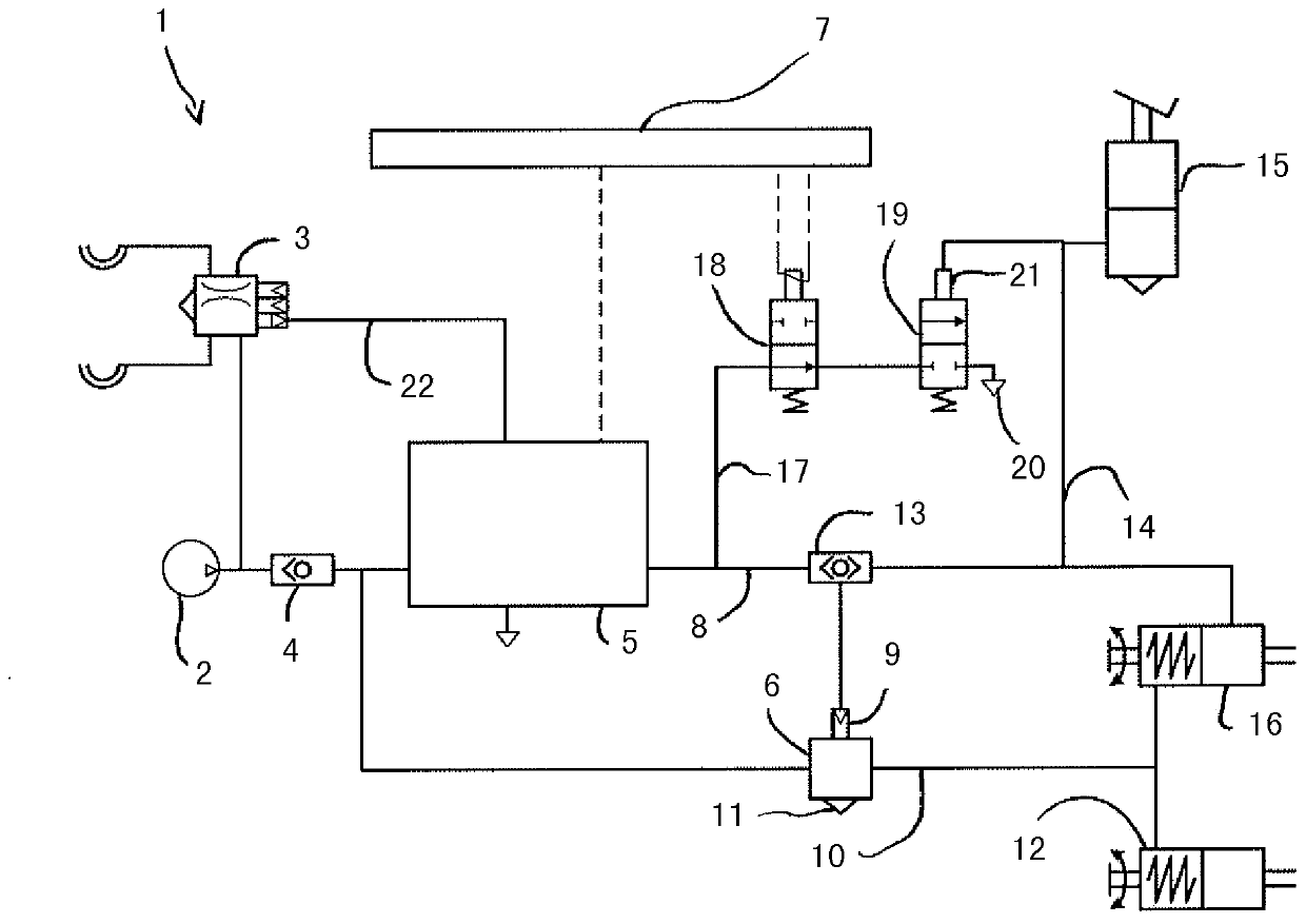
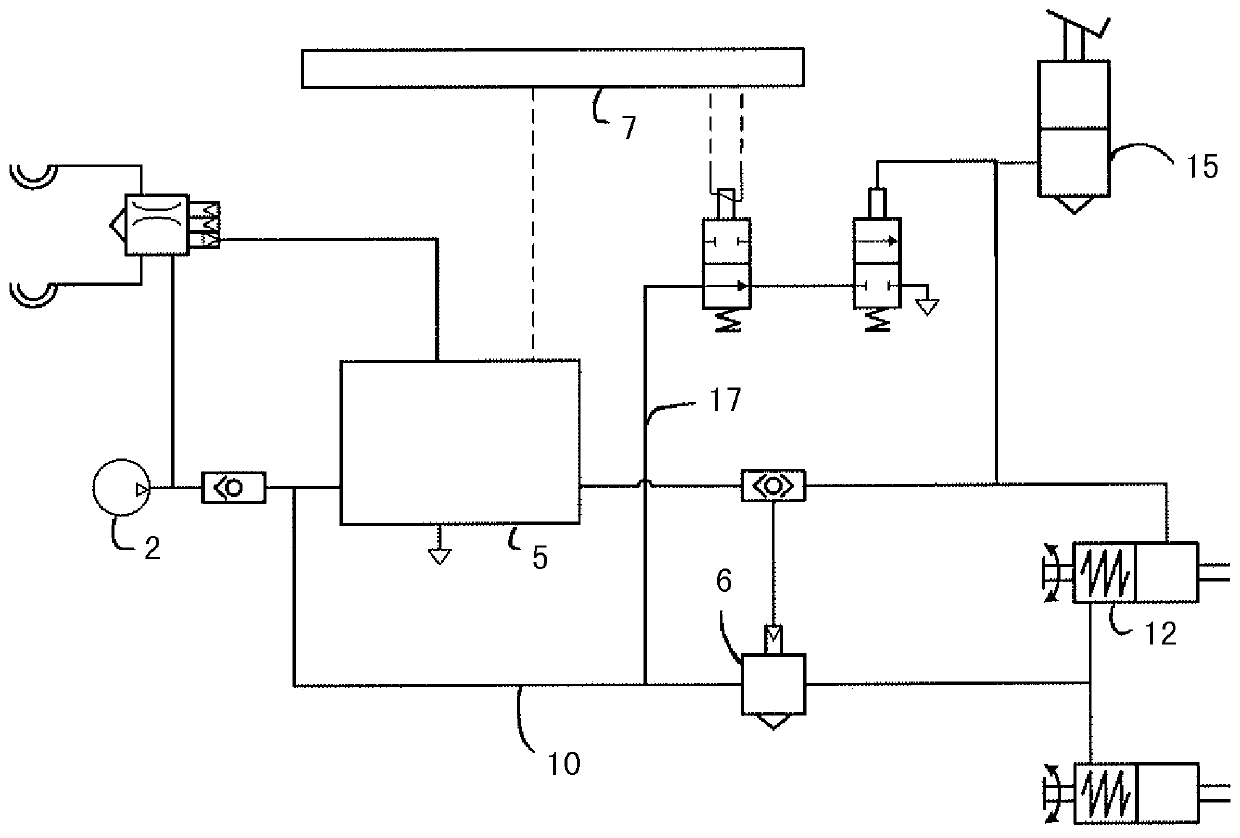
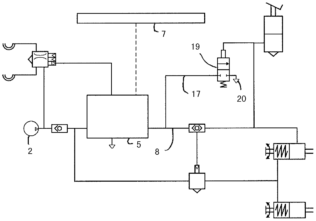
[0027] according to figure 1 , the electro-pneumatic brake control system 1 comprises a compressed air supply unit 2, by means of which, in addition to supplying compressed air to the trailer service brake system 3 (guaranteed by a check valve 4), a parking brake valve assembly is supplied 5 and relay valve 6 supply compressed air.

[0028] Here, the parking brake valve assembly 5 is actuated electronically via an electronic control unit 7 . As long as the control unit 7 works as intended, the air pressure in the control line 8 can be increased or reduced to atmospheric pressure by the control unit, which then acts on the control interface 9 of the relay valve 6, As a result, the supply line 10 is provided on the output side of the relay valve 6 with the same equal air pressure. The supply line 10 is fed into the spring accumulator brake cylinder 12 on the output side of the relay valve 6 so that the corresponding parking brake is released when the compressed air is supplie...


PUM


Abstract

The invention relates to an electro-pneumatic brake control system (1) of a vehicle, comprising an electronic control unit (7) for actuating an electro-pneumatic parking brake valve arrangement (5) supplied with compressed air by a compressed air supply unit (2), a control line (8) emerging therefrom for controlling the compressed air supply and ventilation of a spring brake cylinder (12), a relay valve (6) connected via a supply line (10) to the compressed air supply unit (2) on the input side, and to the spring brake cylinder (12) on the output side, and actuated by the control line (8), for outputting the air pressure applied in the control line (8), and a manually operable, mechanical operating brake actuating element (15) for controlling the compressed air feed and ventilation of an operating brake cylinder (16) via an operating brake supply line (14). In a stable switching state, a mono-stable, pneumatically actuatable control valve (19), comprising a control terminal (21) actuated by the operating brake supply line (14), separates an air outlet opening (20) on the output side terminating into the atmosphere and an venting line (17) on the input side from one another, and in an unstable switching state connects the same with one another. The venting line (17) is suited to vent the spring brake cylinder (12) by actuating the operating brake actuating element (15).

Description

technical field [0001] The invention relates to an electro-pneumatic brake control system of a vehicle, comprising: an electronic control unit for operating an electro-pneumatic parking brake valve assembly supplied with compressed air through a compressed air supply unit; The control line branched from the parking brake valve assembly is used to control the compressed air input and exhaust of the spring accumulator brake cylinder; it is connected to the compressed air supply unit on the input side through the supply line and is connected to the compressed air supply unit on the output side. The relay valve connected to the spring accumulator brake cylinder and controlled by the control pipeline is used to output the air pressure existing in the control pipeline; the mechanical service brake control element that can be manually operated, Used to control the compressed air input and exhaust of the service brake cylinders via the service brake supply line. [0002] The field of...

Claims


Application Information

Patent Timeline
Patent Type & Authority Patents(China)
IPC IPC(8): B60T13/66B60T7/20B60T13/68
CPCB60T7/20B60T13/662B60T13/683
Inventor F·泽曼M·克拉博特
Owner KNORR-BREMSE SYST FUER NUTZFAHRZEUGE GMBH
Learn More