Plasma positioning cutting device based on X-Y-Z-axis system

A positioning cutting, plasma technology, applied in the direction of plasma welding equipment, welding equipment, metal processing equipment, etc., can solve the problem of inability to guarantee cutting stability and cutting precision, parts cannot be directly transported away, and high equipment cost, so as to avoid Personal injury, fast cutting, and the effect of improving processing efficiency

Inactive Publication Date: 2018-03-06
弘毅天承知识产权股份有限公司
View PDF1 Cites 7 Cited by
  • Summary
  • Abstract
  • Description
  • Claims
  • Application Information

AI Technical Summary

Problems solved by technology

[0004] In the prior art, the patent application number CN201210384283.5 discloses a multi-degree-of-freedom cutting device, which includes a rotary table, and a plasma cutting machine and a laser rangefinder are set up on one side of the rotary table. A plasma cutting head adjustment column is erected above the workbench, and a plasma cutting head is installed on the plasma cutting head adjustment column. The laser distance meter is located between the rotary table and the plasma cutting machine. The rotary table includes a support Platform, rotating platform, X, Y coordinate mobile platform, and fixture tooling is installed on the uppermost mobile platform, the said rotating platform is driven by the transmission shaft to rotate above the support platform, said X, Y coordinate moving platform and rotating platform Adjacent platforms are matched with guide rails and guide wheels, and guided by guide rods and guide sleeves. The movement of the X and Y coordinate moving platforms is driven by adjusting handwheels, which can adjust the blanks of parts to be processed with multiple degrees of freedom. Make it coincide with the rotation center line of the equipment; although this technical solution can adjust the blank of the parts to be processed with multiple degrees of freedom, the technical solution still has the following shortcomings: 1. The parts after cutting cannot be directly transported away, and manual labor is required. Take it away, and the laser or spray gun of plasma cutting can easily cause personal injury; 2. The movement of the X and Y coordinate moving platforms is respectively driven by the adjustment handwheel, which cannot guarantee good stability and cutting precision; 3. Need to separate Set up a driving device that drives the rotation of the fixture and drives the transmission of the cut parts, and the equipment cost is high

Method used


Image

  • Plasma positioning cutting device based on X-Y-Z-axis system
  • Plasma positioning cutting device based on X-Y-Z-axis system

Examples


Embodiment Construction

[0026] In order for those skilled in the art to better understand the present invention, the present invention will be further described in detail below in conjunction with the accompanying drawings and the following embodiments.

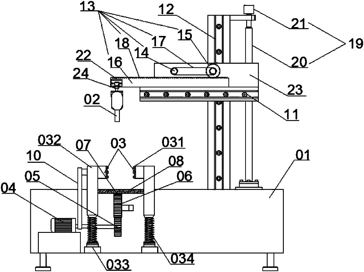
[0027] Please refer to figure 1 with figure 2 As shown, this embodiment provides a plasma positioning cutting device based on the XYZ three-axis system, including a processing table 01, a plasma spray gun 02, a clamping device 03 for clamping the plasma spray gun 02, and a driving plasma spray gun arranged on the processing table 01 02 An XYZ-axis motion assembly that moves freely along the X-axis, Y-axis, and Z-axis directions. Specifically, the clamping device 03 includes two oppositely arranged triangular chucks 031, a support column 032, and a threaded connection with the support column 032. The supporting seat 033 and the triangular chuck 031 are arranged on the supporting parts through bearings, and a damping spring 034 is arranged between t...


PUM


Abstract

The invention discloses a plasma positioning cutting device based on an XYZ three-axis system, relates to the technical field of plasma cutting, and solves the problem in the prior art that parts after cutting cannot be directly transported away and easily cause personal injury; it includes a processing table, a plasma The spray gun, the clamping device for clamping the plasma spray gun, and the XYZ axis movement assembly that is arranged on the processing table to drive the plasma spray gun to move freely along the X-axis direction, the Y-axis direction and the Z-axis direction, and also includes a conveyor belt and drives the clamping device The driving motor that drives the conveyor belt to move while rotating, the driving motor is arranged in the processing table, the output shaft of the driving motor is connected with the clamping device through the toothed belt A, and the output shaft of the driving motor is connected through the rack and pinion mechanism Connect with conveyor belt. By implementing the technical proposal, it is possible to drive the cut part away from the cutting position while driving the jig to rotate, so as to save energy and improve the safety factor.

Description

technical field [0001] The invention relates to the technical field of plasma cutting, and more particularly relates to a plasma positioning cutting device based on an XYZ triaxial system. Background technique [0002] In industrial production, thermal cutting generally includes flame cutting, plasma cutting and laser cutting, among which plasma cutting has a wider cutting range and higher efficiency than gas cutting. The fine plasma cutting technology is close to the quality of laser cutting in terms of material cutting surface quality, but the cost is much lower than laser cutting. Plasma cutting has shown great advantages in saving materials and improving labor production efficiency. Therefore, plasma cutting has been widely used in industrial cutting. [0003] Plasma cutting technology refers to the technology that uses high-speed injection of ionized gas to jet out from the compressed gas port to achieve the cutting effect. The parts are cut and then the metal is melt...

Claims


Application Information

Patent Timeline
Patent Type & Authority Applications(China)
IPC IPC(8): B23K10/00
CPCB23K10/00
Inventor 宋平
Owner 弘毅天承知识产权股份有限公司
Why Eureka
Try Eureka