Oppositely-opening type connecting pipe rotary device

A rotating device, split-type technology, applied in auxiliary devices, welding equipment, tubular objects, etc., can solve the problems of inconvenient disassembly, large workload, low efficiency, etc., and achieve the effects of easy operation, high productivity and simple equipment

Inactive Publication Date: 2018-03-06
李欢
View PDF0 Cites 0 Cited by
  • Summary
  • Abstract
  • Description
  • Claims
  • Application Information

AI Technical Summary

Problems solved by technology

[0002] At present, the existing device rotates the belt pulley, and many other accessory parts need to be dismantled, and the disassembly is very inconvenient, with heavy workload and low efficiency

Method used


Image

  • Oppositely-opening type connecting pipe rotary device

Examples


Embodiment Construction

[0009] The present invention will be further explained below in conjunction with the accompanying drawings.

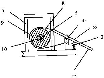
[0010] A split connecting pipe rotating device described in this example is characterized in that it includes a base, a split pipe mold, and a sliding clamp for locking, and the groove width of the base matches the thickness of the belt pulley.

[0011] The split connecting pipe rotating device according to claim 1, characterized in that, the copper pipe blank is installed in the rotating fixture, and the split pipe mold is locked with the rotating fixture, and the sliding fixture is locked and arranged at The side wall of the base penetrates into the groove.

[0012] The split connecting pipe rotating device according to claim 1, wherein the welding end surface of the copper tube blank protrudes, and the copper tube blank and the aluminum tube blank are located on the same axis.

[0013] When maintaining the engine, there is no need to remove other accessory parts, t...


PUM


Abstract

The invention discloses a split-type connecting pipe rotating device, which is characterized in that it includes a base, a split-type pipe mold, and a sliding clamp for locking, and the groove width of the base matches the thickness of the belt pulley; The copper pipe blank is installed in the rotating fixture, and the split pipe mold is locked with the rotating fixture. The sliding fixture is fixed on the side wall of the base and penetrates into the groove; the welding end surface of the copper pipe blank extends It can be seen that the copper tube blank and the aluminum tube blank are on the same axis. The device of the invention has the advantages of simple equipment, high productivity, easy operation, energy saving and good joint quality.

Description

technical field [0001] The invention relates to the field of clamp devices, in particular to a split connecting pipe rotating device. Background technique [0002] At present, many other accessory parts need to be dismantled to rotate the belt pulley in the existing device, and the disassembly is very inconvenient, with heavy workload and low efficiency. When reciprocating friction welding is used to weld metal workpieces, it is often necessary to use considerable force. Contents of the invention [0003] In view of the above problems, the technical problem to be solved by the present invention is to provide a clamping device for nailing. [0004] A split-type connecting pipe rotating device, characterized in that it includes a base, a split-type pipe mold, and a sliding clamp for locking, the groove width of the base matches the thickness of the belt pulley; the copper tube blank is installed Into the rotating fixture, the split pipe mold is locked with the rotating fix...

Claims


Application Information

Patent Timeline
Patent Type & Authority Applications(China)
IPC IPC(8): B23K37/053B23K20/12B23K101/06
CPCB23K37/053B23K20/12B23K37/0533B23K2101/06
Inventor 李欢
Owner 李欢
Why Eureka
Try Eureka