Upper swing arm being simple in structure

A technology with a simple structure and an arm body, applied in the field of the upper swing arm, can solve the problems of low processing precision, high manufacturing difficulty, high cost, etc., and achieve the effects of facilitating production and processing, ensuring shock absorption effect, and avoiding collision damage.

Inactive Publication Date: 2018-03-06
TIANJIN GUANTONG AUTOMOBILE PART MFR
View PDF0 Cites 0 Cited by
  • Summary
  • Abstract
  • Description
  • Claims
  • Application Information

AI Technical Summary

Problems solved by technology

The shape of the swing arm assembly of ordinary cars is relatively simple, and the processing accuracy requirements are low. In order to ensure the stability and durability of the suspension system and meet the requirements of safety and reliability, the strength of the suspension swing arm should be as high as possible, but the higher The strength needs to be provided by a thicker

Method used


Image

  • Upper swing arm being simple in structure

Examples


Embodiment Construction

[0014] In order to make the purpose, technical solutions and advantages of the embodiments of the present invention more clear, the technical solutions in the embodiments of the present invention will be clearly described below in conjunction with the drawings in the embodiments of the present invention.

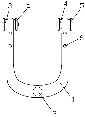
[0015] Such as figure 1 As shown, the upper swing arm with a simple structure described in this embodiment includes a U-shaped upper swing arm body 1, and a mounting shaft hole for installing a ball stud at the center of the upper swing arm body 1. 2. And the first connecting shaft hole (not shown in the figure) and the second connecting shaft hole (not shown in the figure) welded to the two ends of the upper swing arm body 1, the first Anti-collision flanges 5 are provided on the upper swing arm body 1 at both ends of the connecting shaft hole and the second connecting shaft hole, and a plurality of bolts are provided on the two vertical arms of the upper swing arm body 1 ...


PUM


Abstract

The invention discloses an upper swing arm with a simple structure, which comprises a U-shaped upper swing arm body, a mounting shaft hole for installing a ball stud provided at the center of the upper swing arm body, and a mounting shaft hole welded to the upper swing arm body. The first connection shaft hole and the second connection shaft hole at the two ends of the upper swing arm body, the upper swing arm body at both ends of the first connection shaft hole and the second connection shaft hole Anti-collision flanges are all provided, and a plurality of bolt holes are opened on the two vertical arms of the upper swing arm, and the width of the two vertical arms of the upper swing arm is smaller than that of the cross arm of the upper swing arm. width. The upper swing arm with simple structure of the present invention is not only simple in structure and convenient for production and processing, but also reduces the width of the cross arm because the width of the two vertical arms of the upper swing arm is smaller than the width of the cross arm The impact of the concentrated stress at the place on the strength of the product has a greater structural strength.

Description


Claims


Application Information

Patent Timeline
Owner TIANJIN GUANTONG AUTOMOBILE PART MFR
Why Eureka
Try Eureka