
Garment cutting device wide in application range

A technology of application scope and clothing, applied in the cutting of textile materials, textiles and papermaking, etc., can solve the problems of increasing operator burden, reducing production efficiency, low work efficiency, etc., and achieves good cutting effect, convenient operation and simple structure Effect

Pending Publication Date: 2018-03-06
盐城融凡纺织制衣有限公司
View PDF0 Cites 11 Cited by
  • Summary
  • Abstract
  • Description
  • Claims
  • Application Information

AI Technical Summary

Problems solved by technology

[0002] With the continuous development of the economy and the continuous improvement of people's living standards, people have put forward new requirements for the quality and types of various consumer goods to meet people's individual pursuits, and clothing fabrics are one of many consumer goods. As we all know, before the fabric is made into a finished product, it needs to involve many technological processes. Among them, in the process of garment production, when the fabric needs to be cut and cut, the usual way is to rely on the operator to cut the fabric with the help of scissors. Cutting and cutting process, the work efficiency is correspondingly low. When the cloth to be cut is fabric or interlining, since the fabric or interlining is thicker and has greater hardness, pure manual operation will further increase the operation. The burden of personnel, thus reducing the production efficiency, and the existing cutting device can only be applied to a single cutting, the adjustment is very inconvenient

Method used


Image

  • Garment cutting device wide in application range
  • Garment cutting device wide in application range

Examples


Embodiment Construction

[0015] The technical solutions in the embodiments of the present invention will be clearly and completely described below in conjunction with the accompanying drawings in the embodiments of the present invention. Obviously, the described embodiments are only a part of the embodiments of the present invention, rather than all the embodiments.

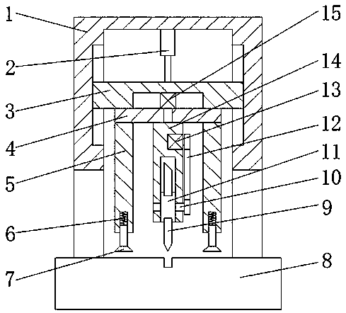
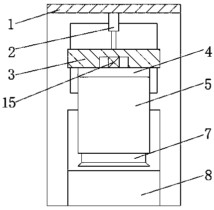
[0016] Reference Figure 1-2 , A clothing cutting device with a wide range of applications, including a frame 1. The two inner walls of the frame 1 are provided with sliding grooves, and the inner walls of the two sliding grooves are slidably connected with the same sliding table 3, and the frame 1 The top inner wall of the hydraulic cylinder 2 is fixed by screws, and one end of the piston rod of the hydraulic cylinder 2 is fixed to the top outer wall of the sliding table 3 by screws. The bottom outer wall of the sliding table 3 is fixed with a fixing plate 4 by screws, and the top of the fixing plate 4 A shaft hole is opened on the outer w...


PUM


Abstract

The invention discloses a garment cutting device wide in application range. The garment cutting device comprises a rack, sliding grooves are formed in the inner walls of the two sides of the rack, andthe inner walls of the two sliding grooves are connected with the same sliding table in a sliding mode; a hydraulic cylinder is fixed to the inner wall of the top of the rack through screws, and oneend of a piston rod of the hydraulic cylinder is fixed to the outer wall of the top of the sliding table through a screw; the outer wall of the bottom of the sliding table is fixedly provided with a fixing plate through screws, a rotating shaft hole is formed in the outer wall of the top of the fixing plate, and a rotating shaft is connected with the inner wall of the rotating shaft hole through abearing; the outer wall of the bottom of the rotating shaft is fixedly provided with a mounting frame through screws. By means of the cooperation of a transmission chain and the rotating shaft, cutters can be quickly replaced; the proper cutters are selected according to different cloth textures, and the cutting effect and the cutting efficiency can be improved; a second motor is arranged so thatthe cutters can rotate according to processing needs to be suitable for cutting at different angles.

Description

Technical field [0001] The invention relates to the technical field of clothing processing equipment, in particular to a clothing cutting device with a wide application range. Background technique [0002] With the continuous development of the economy and the continuous improvement of people’s living standards, people have put forward new requirements for the quality and types of various consumer products to meet people’s individual pursuits. Clothing fabrics are one of many consumer products. As we all know, before the fabric is made into a finished product, many processes are involved. Among them, in the process of garment processing, when the fabric needs to be cut and cut, the usual method is to rely on the operator to use scissors to cut the fabric. Cutting and cutting processing is correspondingly inefficient. When the fabric to be cut is a fabric or interlining, because the fabric or interlining is relatively thick and has a greater hardness, manual operation will further...

Claims


Application Information

Patent Timeline
IPC IPC(8): D06H7/00
CPCD06H7/00
Inventor 洪立龙
Owner 盐城融凡纺织制衣有限公司
Learn More