Eureka AIR delivers breakthrough ideas for toughest innovation challenges, trusted by R&D personnel around the world.

Fabricated reinforced concrete angle brace frame and construction method thereof

A reinforced concrete and construction method technology, applied in truss structures, protective buildings/shelters, building components, etc., can solve the problems of high construction dimensional accuracy, long construction period, complex procedures, etc., and shorten the construction period , small impact on cost, and obvious economic benefits

Pending Publication Date: 2018-03-06
南京百西思建筑科技有限公司
View PDF7 Cites 12 Cited by
  • Summary
  • Abstract
  • Description
  • Claims
  • Application Information

AI Technical Summary

Problems solved by technology

At present, the construction concrete of the prefabricated beam-column of the prior art is poured twice, which will inevitably lead to links such as prefabricated and cast-in-place parts, beam-to-column connections, and column-to-column connections. Disadvantages such as high dimensional accuracy requirements
[0003] There are many coordination problems in the design, prefabricated parts production, on-site installation and concrete pouring of the prefabricated structure, resulting in a long construction period and an increase in cost by 15-30%, which has become a major obstacle to popularization and application.

Method used


Image

  • Fabricated reinforced concrete angle brace frame and construction method thereof
  • Fabricated reinforced concrete angle brace frame and construction method thereof
  • Fabricated reinforced concrete angle brace frame and construction method thereof

Examples


Embodiment Construction

[0036] The present invention will be further described in detail below in conjunction with the drawings and specific preferred embodiments.

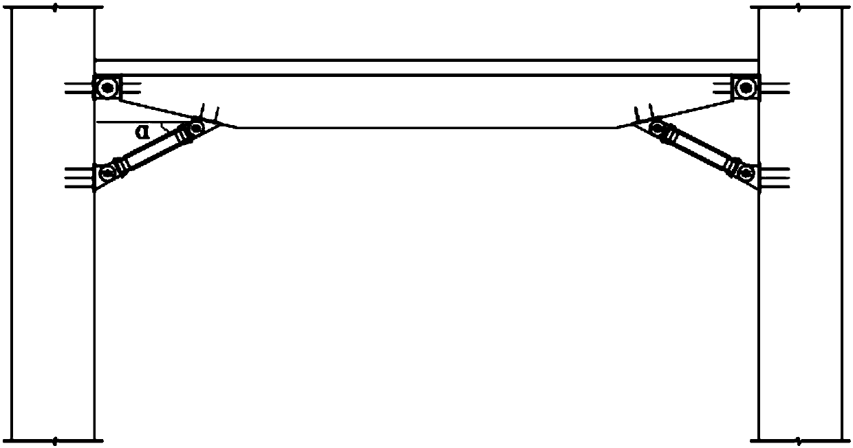
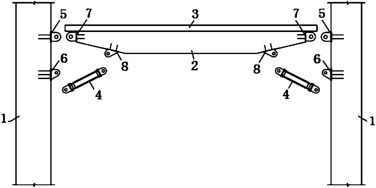
[0037] Such as figure 1 with figure 2 As shown, a fabricated reinforced concrete gusset frame includes a prefabricated column 1, a laminated beam, and an anti-buckling support 4.

[0038] The composite beam is arranged horizontally, and the composite beam includes a precast beam 2 and a post-poured concrete 3 on the top of the precast beam.

[0039] Both ends of the precast beam are preferably gradually decreasing beams with variable cross-sections. The setting of variable cross-section beams is convenient for installation, and can increase the horizontal angle α between the anti-buckling support and the prefabricated composite beam, and the supporting effect is better; in addition, the use of reinforced concrete can be saved.

[0040] The two ends of the precast beam are hinged with the precast columns on both sides, and the bottom of the pre...


PUM


Abstract

The invention discloses a fabricated reinforced concrete angle brace frame and a construction method thereof. The fabricated reinforced concrete angle brace frame comprises precast columns, a laminated beam and anti-buckling supports, the laminated beam comprises a precast beam and post-poured concrete, and the two ends of the precast beam are hinged to the precast columns located on both sides; and one anti-buckling support which is slantly arranged is arranged on each side of the two sides of the bottom of the precast beam, one end of each anti-buckling support is hinged to the bottom of theprecast beam, and the other end of each anti-buckling support is hinged to the corresponding precast column. In the fabricated reinforced concrete angle brace frame, the beam and the columns are connected by adopting pin shafts, and real fabricated construction is realized; and at the same time, under the condition that the borne load is invariable, the height of the beam is greatly reduced, thestorey height of a building is decreased by 5-8%, and the net height of the interior of a house is increased by 200-300 mm. In addition, the precast length of each precast column is not limited by cast-in-place of storeys, the precast length of each precast column can be lengthened, and batches of sleeve grouting connection can be reduced according to requirements such as transportation conditions, so that the construction quality of the columns is improved, and the construction period is shortened.

Description

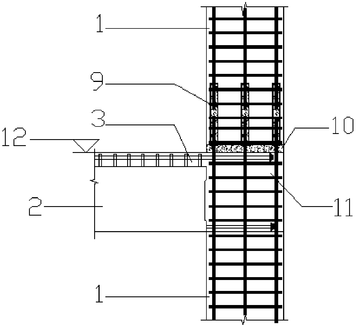
Technical field [0001] The invention relates to the technical field of building structures, in particular to an assembled reinforced concrete gusset frame and a construction method thereof. Background technique [0002] The existing prefabricated reinforced concrete frame structure is no different from the integral cast-in-place concrete structure in terms of design, except that the beams, slabs, and columns become superimposed components. In terms of seismic performance, it is basically equivalent to a cast-in-place reinforced concrete structure, and the beam-column connection model adopts a rigid connection method. Such as image 3 As shown, in the construction, the column adopts prefabricated columns, but the columns in the beam-column node area should be cast-in-place concrete, that is, the post-node cast area 11. The laminated beam and the column are rigidly connected, and the beam steel bars are anchored into the cast-in-situ concrete at the column nodes. In this way, the ...

Claims


Application Information

Patent Timeline
IPC IPC(8): E04B1/21E04B1/98E04H9/02E04C3/20
CPCE04B1/21E04C3/20E04H9/021E04H9/025
Inventor 鲁风勇李小敏
Owner 南京百西思建筑科技有限公司
Why Eureka
Eureka Blog
Learn More