Staged combustion device of with fuel oil cooling flame tube wall surface

A staged combustion and flame cylinder technology, which is applied in combustion chambers, combustion methods, combustion equipment, etc., can solve the problems of the cooling air quality of the flame cylinder and other problems, achieve good mixing effect, excellent atomization and evaporation effects, and increase temperature rise Effect

Pending Publication Date: 2018-03-06
AERO ENGINE ACAD OF CHINA
View PDF4 Cites 10 Cited by
  • Summary
  • Abstract
  • Description
  • Claims
  • Application Information

AI Technical Summary

Problems solved by technology

At the same time, the increase in the pressure ratio and efficiency of the engine compressor leads to a further increase in the inlet temperature of the combustion chamber, which means that the quality of the cooling air used for the combustion chamber flame tube is reduced

Method used


Image

  • Staged combustion device of with fuel oil cooling flame tube wall surface

Examples


Embodiment Construction

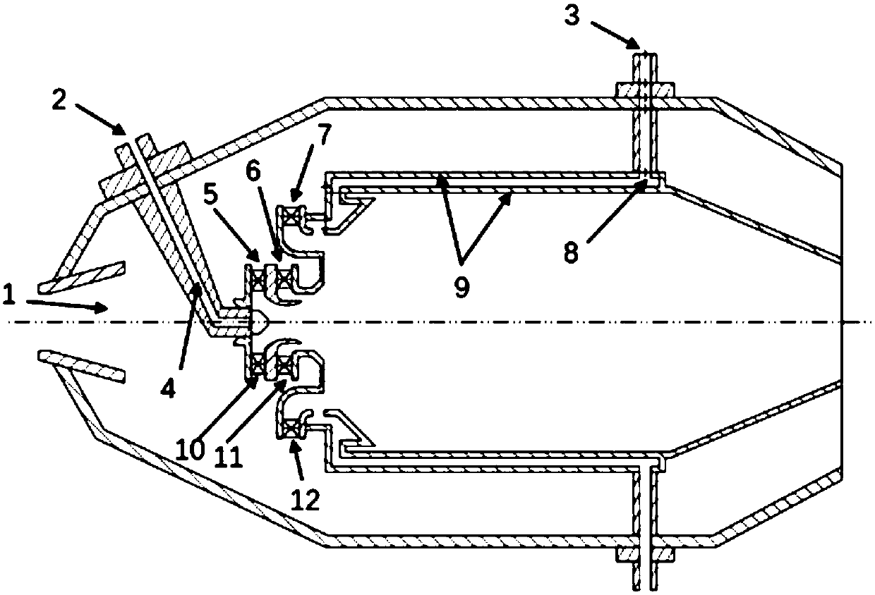
[0032] figure 1 It is a schematic diagram of the structural principle of the staged combustion device of the fuel oil cooling flame tube wall surface of the present invention, combined below figure 1 The staged combustion device for cooling the wall surface of the flame tube with fuel oil of the present invention is described in detail.

[0033]The staged combustion device of the fuel oil cooling flame tube wall of the present invention comprises an air inlet 1, a main combustion level fuel inlet 3, a main combustion level fuel channel 8, a flame tube circumferential side wall 9 and a main combustion level air channel 7, and the main combustion level fuel The inlet 3 is located at the middle and rear part of the staged combustion device; the outlet of the main combustion stage fuel passage 8 is close to the outlet of the main combustion stage air passage 7; the part of the main combustion stage fuel passage 8 passing through the flame cylinder is limited by the flame cylinder ...


PUM


Abstract

The invention provides a staged combustion device with fuel oil cooling a flame tube wall surface. The staged combustion device with the fuel oil cooling the flame tube wall surface comprises a main combustion stage fuel inlet, a main combustion stage fuel channel, a flame tube circumferential side wall and a main combustion stage air channel. The main combustion stage fuel inlet is located on themiddle back portion of the outer wall of the staged combustion device. One end of the main combustion stage fuel channel communicates with the main combustion stage fuel inlet, and the other end of the main combustion stage fuel channel is adjacent to an outlet of the main combustion stage air channel. The flame tube circumferential side wall is a double-layered wall surface.

Description

technical field [0001] The invention belongs to the technical field of combustion chambers of gas turbines, and in particular relates to a staged combustion device for cooling the wall surface of a flame cylinder with fuel oil. Background technique [0002] With the continuous improvement of aero-engine performance requirements, the engine cycle parameters and component efficiency will further increase, and the technical requirements of the engine combustion chamber will also continue to increase. The development trend of the new-generation engine combustion chamber is mainly manifested in: the continuous improvement of the performance of the combustion chamber, the continuous shortening of the length of the combustion chamber, the substantial increase of the aerodynamic load, the significant enhancement of the heat capacity, and the greatly extended service life. [0003] In order to meet the power performance of future aero-engines, aero-engines require the components of t...

Claims


Application Information

Patent Timeline
IPC IPC(8): F23R3/30F23L15/04
CPCF23L15/04F23R3/30Y02E20/34
Inventor 杨谦王慧汝黄夏薛然然李瑞明
Owner AERO ENGINE ACAD OF CHINA
Why Eureka
Try Eureka