Method for measuring residual stress on surface of milling part based on strain change and inverse inference method

A technology of residual stress and milling, which is applied to force/torque/work measuring instruments, measuring devices, instruments, etc., can solve problems such as inconsistent stress values ​​and inconsistent rigidity of parts, and achieve the effect of simple operation

Inactive Publication Date: 2018-03-06
NANJING UNIV OF TECH +1
View PDF5 Cites 4 Cited by
  • Summary
  • Abstract
  • Description
  • Claims
  • Application Information

AI Technical Summary

Problems solved by technology

[0004] For the research of surface residual stress, it often starts from the measurement of its value changing with depth. At present, the relatively mature measurement technology is X-ray method combined with delamination method. However, due to the distribution of the final surface residual stress value of parts to a large extent It is affected by the rigidity of the parts, so even if the same part material, the same processing method, processing parameters, and processing conditions, due to the inconsistency of the rigidity of the parts, it may eventually lead to inconsistent stress values ​​after reaching self-balance, so X-ray The surface residual stress value of a part finally measured by the method combined with the delamination method is not representative.

Method used


Image

  • Method for measuring residual stress on surface of milling part based on strain change and inverse inference method
  • Method for measuring residual stress on surface of milling part based on strain change and inverse inference method
  • Method for measuring residual stress on surface of milling part based on strain change and inverse inference method

Examples


Embodiment Construction

[0055] The technical solution of the present invention will be described in detail below in conjunction with the accompanying drawings.

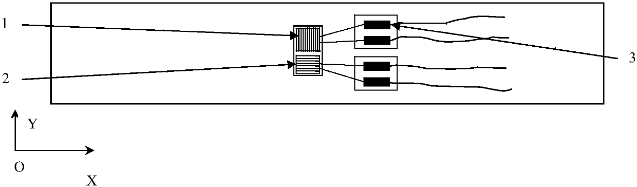
[0056] Firstly, a two-way strain gauge is pasted on the back of the machined surface of the part to measure the change of the strain in the X and Y directions on the back when the residual stress layer is corroded and peeled off.

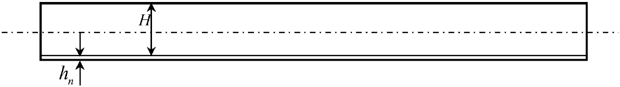
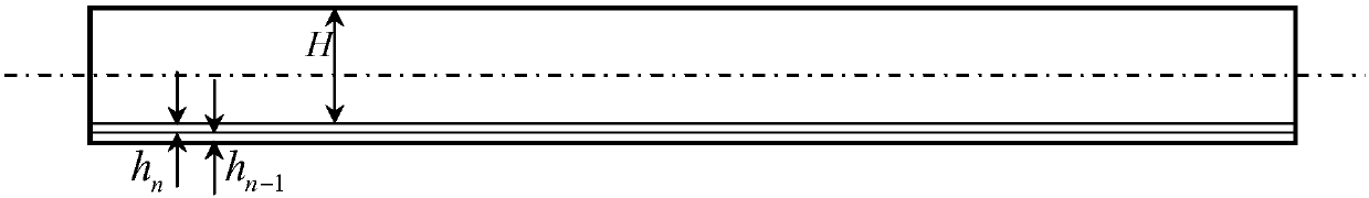
[0057]The calculation of the bending moment caused by the residual stress is mainly based on the magnitude of the stress in the stress layer and the distance between the stress layer and the neutral layer. The neutral layer is always located in the geometric middle of the part, which is removed for each corrosion After a layer of material, the position of the neutral layer of the part will change accordingly. Therefore, after each layer of material is removed, the stress of the remaining part changes due to its distance from the neutral layer, so the bending moment caused by it will also change. Corresponding chan...


PUM


Abstract

The invention discloses a method for measuring the residual stress on the surface of a milling part based on strain change and an inverse inference method, which belongs to the field of mechanical engineering. In the traditional measurement process of the residual stress on the surface of a milling part based on an X-ray method, the measured residual stress often reaches the stress value after theequilibrium state, and the equipment used is expensive. In the invention, the strain change of the back of a milled side in the stripping process of a residual stress layer on the surface is measured. Meanwhile, in view of the transformation of bending moment caused by the residual stress in the remaining residual stress layer after each stripping due to the position change of the neutral layer,calculation is carried out from the bottommost layer and inverse inference is carried out step by step from bottom to top until the residual stress value in the topmost layer is calculated. Thus, themeasurement of surface residual stress changing with depth in the whole milling process is completed. The equipment required in the whole process is inexpensive, and the operation is simple. The measured value can be used to accurately predict the deformation of stress of various shapes and sizes caused by the surface residual stress and the distribution of the actual residual stress inside a partafter the internal stress eventually reaches equilibrium.

Description

Technical field: [0001] The invention relates to a method for measuring the residual stress on the surface of a milled part based on the measurement of the strain change on the surface of the part and a reverse deduction method, which belongs to the stress measurement method in the field of mechanical engineering. Background technique: [0002] Residual stress, that is, internal stress, its nature and size will seriously affect the service performance and life of parts. In industry, manufacturers often pay more attention to improving the beneficial effect of residual stress and reducing its harmful effect, thereby further improving product quality. . [0003] During the cutting process of metal parts, a layer of residual stress layer will be formed on the surface of the final part. In this stress layer, the distribution of residual stress is very shallow, generally not exceeding 0.2mm, but in the depth direction. High rate of change, the size and nature of the stress value ...

Claims


Application Information

Patent Timeline
IPC IPC(8): G01L5/00
CPCG01L5/0047
Inventor 孟龙晖方成刚王华黄筱调
Owner NANJING UNIV OF TECH
Why Eureka
Try Eureka