

Test device for testing bituminous pavement shear failure
A technology of shear failure and test device, which is applied in the direction of measuring device, using a stable shear force to test the strength of materials, instruments, etc., can solve the lack of test device for the detection of unchecked shear stress, shear failure, and pavement horizontal force and other problems, to achieve the effect of simple structure and convenient operation
- Summary
- Abstract
- Description
- Claims
- Application Information
AI Technical Summary
Problems solved by technology
Method used
Image

Examples
Embodiment Construction
[0018] The present invention is described in further detail below in conjunction with accompanying drawing:
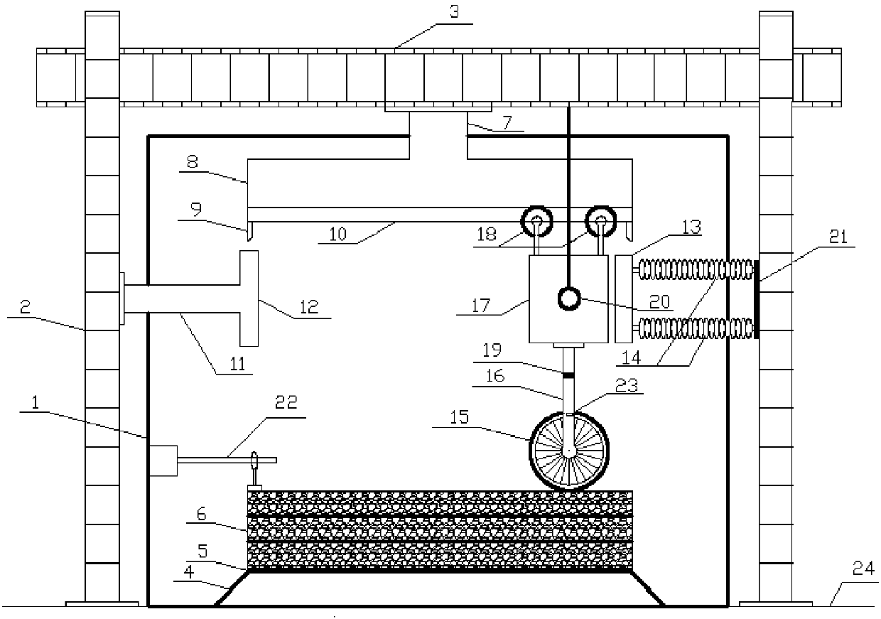
[0019] refer to figure 1 , the test device for testing asphalt pavement shear failure according to the present invention comprises a control system, a test bench 24, a reaction force frame positioned on the test bench 24 and a temperature control box 1, a sample platform for placing the sample 6 to be tested 4, be positioned at the wheel 15 on the sample to be tested 6, be used to drive the lateral driving device that the wheel 15 moves on the surface of the sample to be tested 6, be used to make the vertical force that the wheel 15 exerts pressure on the surface of the sample to be tested 6 device, a displacement sensor 22 for detecting the horizontal displacement of the surface of the sample 6 to be tested, a lateral pressure sensor 21 for detecting the thrust of the lateral drive device on the wheel 15, and a pressure sensor for detecting the pressure applied by the...
PUM
 Abstract
Description
Claims
Application Information