Power module aging device

An aging device and power module technology, applied in the direction of power supply testing, etc., can solve the problems of low power consumption, low cost, large area of ​​the aging room, and the aging room is too cumbersome, etc. space saving effect

Active Publication Date: 2018-03-06
常州能动新能源科技有限公司
View PDF11 Cites 4 Cited by
  • Summary
  • Abstract
  • Description
  • Claims
  • Application Information

AI Technical Summary

Problems solved by technology

[0003] Existing aging rooms generally require special sites to be built and operated by professionals. The aging rooms occupy a large area, have high maintenance costs, and are troublesome to operate. For laboratory operations of some small mobile power supplies, such aging rooms are obviously too cumbersome , does not meet the requirements of low power consumption and low cost

Method used


Image

  • Power module aging device
  • Power module aging device
  • Power module aging device

Examples


Embodiment

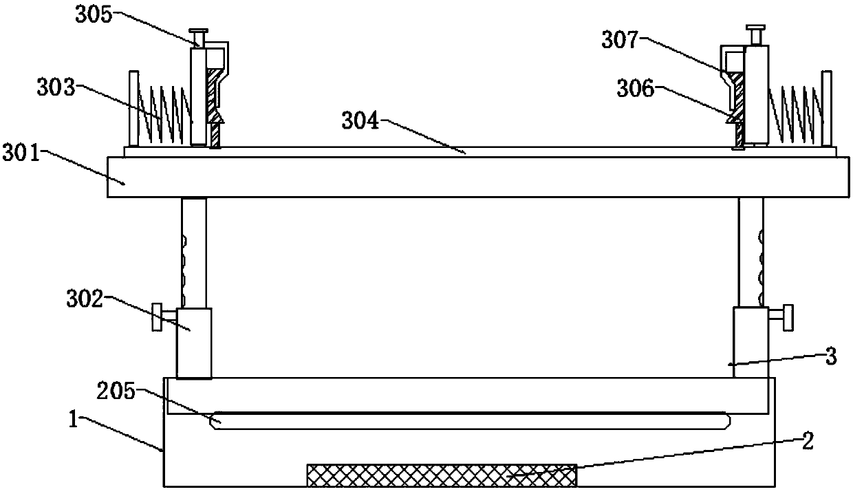
[0027] Such as figure 1 As shown, the present invention provides an aging device for power modules, including an aging box 1, the aging box 1 is made of polytetrafluoroethylene into a rectangular box, which has good insulation protection performance and is easy to move and carry; the inside of the box It is divided into two layers by insulating partitions. The aging test circuit 2 is installed at the bottom of the box, and the power supply fixing mechanism 3 is installed above the partition. The power supply fixing mechanism 3 is used to fix the power supply to be aged. Aging test and corresponding analysis and processing;

[0028] The power supply fixing mechanism 3 includes a fixed base plate 301, the fixed base plate 301 is made of an insulating plastic plate, mounting holes are drilled at the four corners of the fixed base plate 301, and a telescopic support frame 302 is inserted into the mounting hole, and the telescopic support frame The other end of 302 is fixedly embe...


PUM


Abstract

The invention discloses a power module aging device, which comprises an aging box. The aging box is divided by an insulated separator plate into a lower aging test circuit and an upper power fixationmechanism. The power fixation mechanism comprises a fixation bottom plate. The four corners of the fixation bottom plate are respectively provided with a telescopic support frame. The upper surface ofthe fixation bottom plate is provided with a slide guide. The two ends of the slide guide are internally and vertically embedded by a spring fixation plate. The top end of the spring fixation plate is embedded by a wiring column. The aging test circuit comprises a core controller and a power supply battery. The core controller is connected with a battery management chip. A GPIO port of the core controller is connected with a voltage stabilization transformation module through a wire. The input end of the voltage stabilization transformation module is connected to the output end of the power supply battery and outputs an electric signal to the wiring column. The driving end of the core controller is connected with an electric heating pipe. The power module aging device is small in size andconvenient to move and accommodate, can carry out real-time adjustment according to a power supply under test, is high in environment adaptability and is simple, safe and convenient to use.

Description

technical field [0001] The invention relates to the field of power testing equipment, in particular to an aging device for a power module. Background technique [0002] The aging test project refers to the process of simulating the various factors involved in the actual use conditions of the product to carry out corresponding condition strengthening experiments on the aging of the product. The aging of the power supply refers to simulating a test environment under high temperature and harsh conditions. High-performance electronic products are burned for a long time to improve the production process of product safety, stability and reliability. Nowadays, the aging of power supplies is generally carried out in professional aging rooms. The aging room, also known as the burn-in room, is aimed at the simulation of high-performance electronic products (such as: complete computer, display, terminal, automotive electronic products, power supply, motherboard, monitor, switching char...

Claims


Application Information

Patent Timeline
Patent Type & Authority Applications(China)
IPC IPC(8): G01R31/40
CPCG01R31/40
Inventor 鹿婷婷
Owner 常州能动新能源科技有限公司
Why Eureka
Try Eureka