Coiled lithium ion battery, coiled core and manufacturing method of coiled lithium ion battery

A technology of lithium-ion batteries and lithium-ion batteries, which is applied in the manufacturing field of wound-type lithium-ion battery cores and wound-type lithium-ion batteries, can solve problems such as narrow paths, long soaking time, and long baking time, and achieve Simple path, good infiltration effect and short baking time

Pending Publication Date: 2018-03-06
HANGZHOU FUTURE POWER TECH
View PDF0 Cites 8 Cited by
  • Summary
  • Abstract
  • Description
  • Claims
  • Application Information

AI Technical Summary

Problems solved by technology

[0002] Existing winding structure batteries, please refer to Figure 1 to Figure 5 , the current collectors of the positive electrode sheet 01 and the negative electrode sheet 05 are aluminum foil and copper foil respectively, and neither liquid nor gas can pass directly through its winding core 08, and the electrolyte can only enter from the narrow passage at the head and tail after baking before liquid injection. Core 08, the path is narrow, not smooth, and the baking time is long. Generally, it takes 24 hours to vacuumize and bake in an oven at 80°C to reach the internal moisture ≤ 200ppm. It is difficult to drain the electrolyte. After the electrolyte enters the battery airbag 010, It can only infiltrate from the outside of the head of the winding core 08, and then enter the inner pole piece and diaphragm. Generally, it takes about 36 hours for electrolyte infiltration to be relatively sufficient. The required infiltration time is long, the infiltration effect is poor, and the infiltration is uneven. lead to poor battery performance

Method used


Image

  • Coiled lithium ion battery, coiled core and manufacturing method of coiled lithium ion battery
  • Coiled lithium ion battery, coiled core and manufacturing method of coiled lithium ion battery
  • Coiled lithium ion battery, coiled core and manufacturing method of coiled lithium ion battery

Examples


Embodiment Construction

[0038] The following will clearly and completely describe the technical solutions in the embodiments of the present invention with reference to the accompanying drawings in the embodiments of the present invention. Obviously, the described embodiments are only some, not all, embodiments of the present invention. Based on the embodiments of the present invention, all other embodiments obtained by persons of ordinary skill in the art without making creative efforts belong to the protection scope of the present invention.

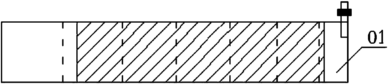
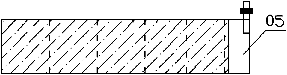
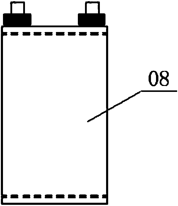
[0039] The core of the present invention is to provide a wound lithium electronic battery core that can shorten the baking time and improve the wetting effect when manufacturing the battery. Another core of the present invention is to provide a wound lithium electronic battery comprising the above wound lithium electronic battery core, which has a shorter baking time and better wetting effect during manufacture. Another core of the present invention is to prov...


PUM


Abstract

The invention discloses a coiled lithium ion battery coiled core, a coiled lithium ion battery and a manufacturing method of the coiled lithium ion battery. The coiled lithium ion battery coiled corecomprises a coiled core body, wherein the coiled core body comprises a positive plate and a negative plate which are coiled with each other in a matching way; the positive plate is provided with positive plate openings; the negative plate is provided with negative plate openings; the positive plate openings and the negative plate openings are arranged in a staggered way along a radial direction toform channels passing through the coiled core body; at least two channels are formed; on the same channel, the areas of the positive plate openings are larger than the areas of the negative plate openings. In the coiled core, the positive plate is provided with the positive plate openings, the negative electrode plate is provided with the negative plate openings, and specific channels are formedon the coiled core body after coiling, so that coiled core body gas can smoothly pass through and be discharged from a battery system during baking, and the baking time can be shortened; meanwhile, apath from electrolyte infiltration to the coiled core body can be shortened through the channels, so that the infiltration effect is improved.

Description

technical field [0001] The invention relates to the technical field of lithium-ion batteries, in particular to a wound-type lithium-ion battery core. In addition, the present invention also relates to a wound lithium ion battery comprising the above wound lithium ion battery core and a manufacturing method of the wound lithium ion battery using the above wound lithium ion battery core. Background technique [0002] Existing winding structure batteries, please refer to Figure 1 to Figure 5 , the current collectors of the positive electrode sheet 01 and the negative electrode sheet 05 are aluminum foil and copper foil respectively, and neither liquid nor gas can pass directly through its winding core 08, and the electrolyte can only enter from the narrow passage at the head and tail after baking before liquid injection. Core 08, the path is narrow, not smooth, and the baking time is long. Generally, it takes 24 hours to vacuumize and bake in an oven at 80°C to reach the inter...

Claims


Application Information

Patent Timeline
Patent Type & Authority Applications(China)
IPC IPC(8): H01M4/13H01M10/0525H01M10/0587
CPCH01M4/13H01M10/0525H01M10/0587Y02E60/10Y02P70/50
Inventor 郑长明陈先学郭也平郑洪荣浦坚
Owner HANGZHOU FUTURE POWER TECH
Why Eureka
Try Eureka