Overturning structural drill clamp
A technology of jig and clamping body, applied in the direction of drilling dies for workpieces, etc., can solve the problems of increasing the processing cost of parts, affecting the processing accuracy of parts, and increasing the rhythm of the process, so as to ensure the processing accuracy, reduce the processing time, and reduce the processing time. cost effect
- Summary
- Abstract
- Description
- Claims
- Application Information
AI Technical Summary
Problems solved by technology
Method used
Image

Examples
Embodiment Construction
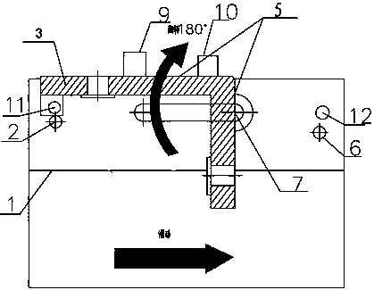
[0007] exist figure 1 Attach the "L" surface of the part to the fixed surface (5) of the fixed part on the "L"-shaped drill template (3) and position it with the positioning pin (9) on the drill template and use the clamping mechanism (10) on the drill template ) to clamp. Then pull the fixed "L"-shaped drill template (3) to the right along the sliding groove (7) on the clamp body (1), so that one end of the "L"-shaped drill template (3) will not be positioned by the left The stop pin (2) is blocked and cannot be turned clockwise. The parts fixed surface of " L " type parts will be turned over 180 ° clockwise and the positioning stop pin (6) horizontal direction on the right is blocked like this, clamp body and drilling template are locked with locking mechanism (12). After finishing the drilling of the first surface, loosen the locking mechanism (12), turn it counterclockwise 90°, make the other surface horizontal to the left stop pin (2), and lock it with the locking mecha...
PUM
 Abstract
Description
Claims
Application Information
 - Generate Ideas
- Intellectual Property
- Life Sciences
- Materials
- Tech Scout
- Unparalleled Data Quality
- Higher Quality Content
- 60% Fewer Hallucinations
Browse by: Latest US Patents, China's latest patents, Technical Efficacy Thesaurus, Application Domain, Technology Topic, Popular Technical Reports.
© 2025 PatSnap. All rights reserved.Legal|Privacy policy|Modern Slavery Act Transparency Statement|Sitemap|About US| Contact US: help@patsnap.com