Flood drainage system of dry-type tailing reservoir

A tailings pond and dry-type technology, which is applied in the direction of waterway system, sewage discharge, drainage structures, etc., can solve the problems of loss of storage capacity, high construction cost of flood drainage shaft, and high construction difficulty, so as to increase storage capacity, shorten flood discharge time, The effect of increasing flood control storage capacity

Inactive Publication Date: 2018-03-09
SHENYANG ALUMINIUM MAGNESIUM INSTITUTE
View PDF4 Cites 2 Cited by
  • Summary
  • Abstract
  • Description
  • Claims
  • Application Information

AI Technical Summary

Problems solved by technology

At present, the methods that can be adopted are to increase the slope of the beach surface or increase the diameter of the flood discharge shaft, but these

Method used


Image

  • Flood drainage system of dry-type tailing reservoir
  • Flood drainage system of dry-type tailing reservoir
  • Flood drainage system of dry-type tailing reservoir

Examples


Embodiment Construction

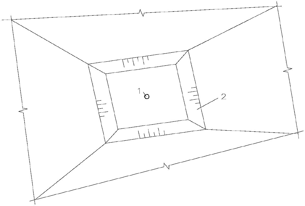
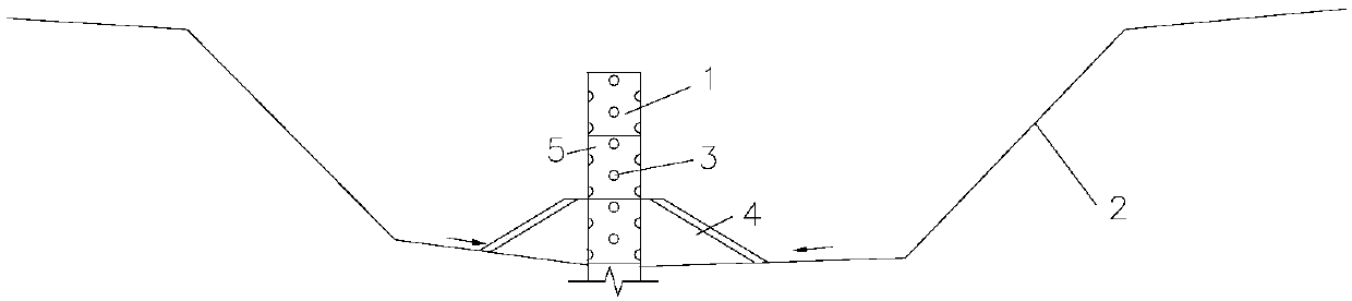
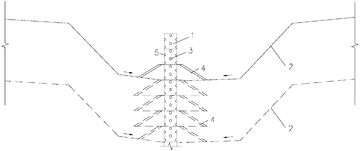
[0031] Such as Figure 1-Figure 5 Shown, the specific structure of the flood discharge system of the dry tailings pond of the present invention is as follows:

[0032] A flood control pool 2 is built around the flood discharge shaft 1. The flood discharge shaft 1 adopts a metal structure well body and a reinforced concrete well seat. The well body is opened with a backwater hole 3, which is arranged in a plum blossom shape. The outer side of the backwater hole 3 is connected with the flange plate 6 , and the outer side of the joint between the flange plate 6 and the backwater hole 3 is covered with a geotextile 7 . The flange plate 6 is an annular steel plate, the flange plate 6 and the return hole 3 are connected by bolts, and the outer layer of the flange plate 6 is welded with steel mesh 8 ( Figure 4 , Figure 5 ).

[0033] The height of the flood discharge shaft 1 exposed to the flood control pool 2 is 4 to 5 meters, and the bottom 2 to 3 meters of the exposed part is ...


PUM

PropertyMeasurementUnit
Plane areaaaaaaaaaaa

Abstract

The invention relates to the flood drainage field of dry-type tailing reservoirs, in particular to a flood drainage system suitable for a dry-type tailing reservoir using an upstream method. The flooddrainage system comprises a flood drainage vertical shaft, a flood regulation water collection pond, water return holes and an inverted filter layer. The concrete structure of the flood drainage system is characterized in that the flood regulation water collection pond is built around the flood drainage vertical shaft; the flood drainage vertical shaft is in the up-down combination structure composed of a shaft body with a metal structure and a reinforced concrete shaft seat; the water return holes are arranged in the shaft body; and the inverted filter layer is installed around the shaft body. The invention is especially adapted to the flood drainage system suitable for the dry-type tailing reservoir using the upstream method. Therefore, the flood regulation water collection pond collects flood and rapidly increases the depth of flood at the flood drainage vertical shaft. In this sense, the flood drainage vertical shaft quickly enters the state of weir flow at the shaft mouth. As a result, a flood drainage capability is increased, flood drainage time is reduced and all floods inside the tailing reservoir are drained out. Therefore, flood infiltration of the reservoir is reduced.Weak intercalated layers of saturated tailings or unstable phreatic lines due to great infiltration depth of floods are avoided.

Description

technical field [0001] The invention relates to the field of flood discharge of dry tailings ponds, in particular to a flood discharge system suitable for upstream dry tailings ponds. Background technique [0002] The upstream method of dry tailings pond drainage generally adopts the central flood drainage method of flood drainage shaft and flood drainage culvert, that is, the well body and well seat of the flood drainage shaft are built with reinforced concrete structures, and the flood drainage shaft and reinforced concrete flood drainage culvert Connected, and then the flood is exported out of the reservoir through the flood discharge culvert. When the tailings pond encounters flood conditions, the highest flood water level is generally 3 to 5 meters, and the flood discharges through the return hole on the shaft of the flood discharge shaft. Due to the small height of the flood water level and the small area of ​​the return hole, the flood discharge The discharge rate of...

Claims


Application Information

Patent Timeline
IPC IPC(8): E03F5/04E03F5/10E03F5/14E03F1/00
CPCE03F1/002E03F5/04E03F5/10E03F5/106E03F5/14
Inventor 乔英卉姜兴东艾纯志
Owner SHENYANG ALUMINIUM MAGNESIUM INSTITUTE
Why Eureka
Try Eureka