
System for hydraulically actuating parking lock

一种液压致动、驻车锁的技术,应用在流体压力致动系统组件、制动安全系统、流体压力致动装置等方向,能够解决昂贵、滑阀损坏等问题

Active Publication Date: 2018-03-09
GKN AUTOMOTIVE LTD BIRMINGHAM
View PDF7 Cites 5 Cited by
  • Summary
  • Abstract
  • Description
  • Claims
  • Application Information

AI Technical Summary

Problems solved by technology

The disadvantage of such a system is that, in order for it to be possible to use the different line sections leading to the actuator in a targeted manner as pressure feed line or return line, relatively expensive 4 / 2-way slide valves have to be provided
Also, this design results in the supplied spool valve being susceptible to damage from contamination within the line section
In addition, to provide a latching device actuated by the control device, which prevents the prestressed actuator from being pressed back into the locked position, this latching device must be activated additionally and causes damage to the components and installation Additional Space Requirements

Method used


Image

  • System for hydraulically actuating parking lock
  • System for hydraulically actuating parking lock

Examples


Embodiment Construction

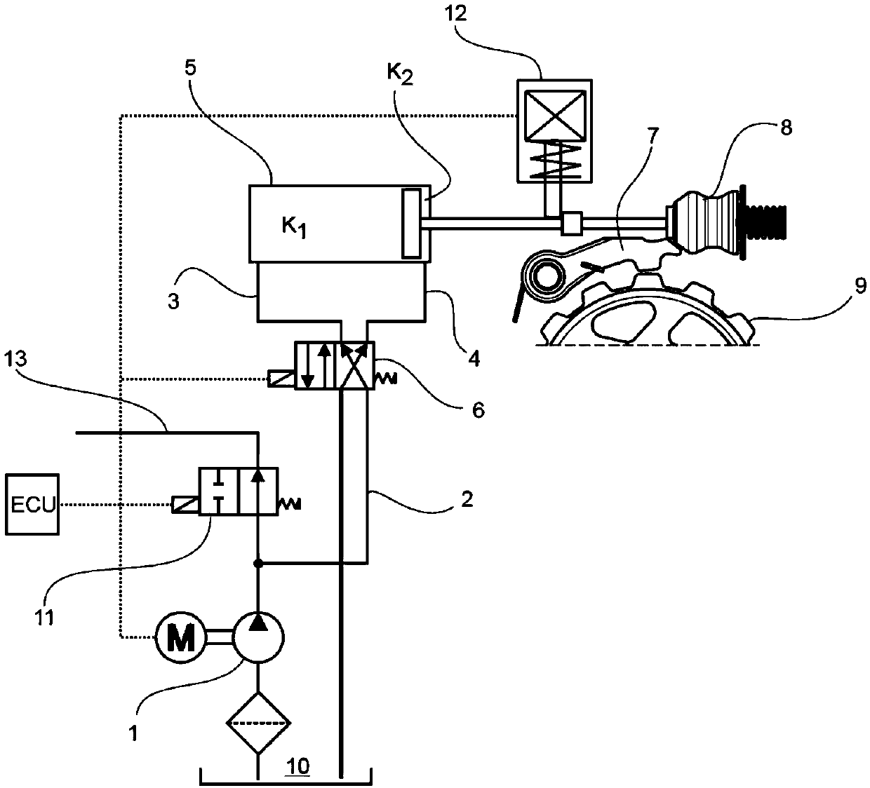
[0024] FIG. 1 shows an idea basically known from the prior art for hydraulically actuating a parking lock of a motor vehicle.

[0025] Hydraulic pressure is generated in a pressure line 2 by means of a pumping device 1 driven by an electric motor M. The pressure line is connected to a solenoid-actuatable 4 / 2-way spool valve 6 (4 / 2-way "spool solenoid valve"), and by means of switching of the spool valve 6, the first line section 3 or the second line section 4 can optionally be used as a pressurized feed line to the actuator 5, while a corresponding further line section serves as a substantially unpressurized return line.

[0026] When hydraulic pressure is applied to the first line section 3 , which corresponds to the position of the slide valve 6 shown in FIG. 1 , the parking lock is switched by the actuator 5 into the released position. In this release position, the engagement lever 7 of the parking lock, which is prestressed by the spring, is disengaged from the correspond...


PUM


Abstract

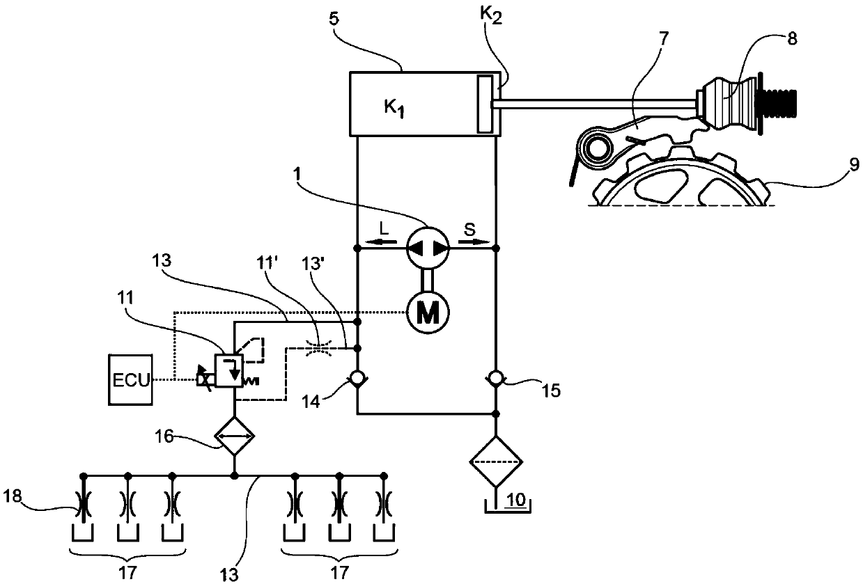
In order to provide a hydraulic actuating system for actuating a parking lock of a motor vehicle, which hydraulic actuating system manages with as few components as possible which are simple, robust,relatively insusceptible to faults and inexpensive, with a simultaneously low installation space requirement, and the hydraulic layout of which hydraulic actuating system makes a simple actuation anda simple movement possible for locking and unlocking the parking lock, it is provided that a pumping device which can operate bidirectionally with a locking delivery direction and with a releasing delivery direction is used as pumping device, and check valves are arranged in the hydraulic circuit in such a way that, by way of actuation of the pumping device in the locking delivery direction, the parking lock moves into the locked position and, upon actuation of the pumping device in the releasing delivery direction, the parking lock moves into the released position.

Description

technical field [0001] The invention relates to a hydraulic actuation system for actuating a parking lock of a motor vehicle, comprising: [0002] an actuator for switching the parking lock from a released position to a locked position and / or from a locked position to a released position, [0003] pumping means for generating hydraulic pressure for switching the parking lock to a locked or released position by said actuator, [0004] a hydraulic circuit through which the pumping means is connected to the actuator, a first line section and a second line section provided in the hydraulic circuit, these line sections being based on the actuation of the actuation system The way acts at least in sections as a pressure feed line to the actuator or as a return line away from the actuator. [0005] The invention also contemplates a motor vehicle having a hydraulic actuation system of this type, a method of actuating a system of this type, a computer program product directed to an el...

Claims


Application Information

Patent Timeline
Patent Type & Authority Applications(China)
IPC IPC(8): F16H63/34F15B11/08F15B13/04F15B13/16F15B21/02
CPCF15B11/08F15B13/04F15B13/16F15B21/02F16H63/3483F15B2211/205B60T1/062B60T13/662B60T17/22F16D63/006B60T1/005B60T13/686F16H63/3475B60T13/148B60T17/02B60T17/04
Inventor R·默尔曼S·米巴赫
Owner GKN AUTOMOTIVE LTD BIRMINGHAM
Learn More