
Dryer and dryer control method

A dryer and housing technology, applied in the dryer and dryer control, drying bathroom space or the user's body dryer field, can solve the problem of affecting the air supply pressure, unable to meet the preferences, generating noise, etc., to achieve Eliminates wear on rotating parts, reduces the burden of sterilization work, and solves cost problems

Active Publication Date: 2020-01-10
LG ELECTRONICS INC
View PDF5 Cites 0 Cited by
  • Summary
  • Abstract
  • Description
  • Claims
  • Application Information

AI Technical Summary

Problems solved by technology

[0004] The drying machine structure of the prior art as described above has the problem that it is difficult to operate in various modes according to the user's needs.
For example, prior art dryers are not easy to control the air volume and direction in various modes when drying the bathroom space and when drying the user's body
This can result in skin being damaged by excessive drying when drying the body after a shower, or the bathroom space being dried out less than expected
In addition, the drying machine in the prior art can only dry the bathroom space, but cannot remove bacteria and viruses in the bathroom, so there is a problem that it is necessary to purchase an additional device for removing bacteria and viruses in the bathroom, or directly carry out sterilization treatment
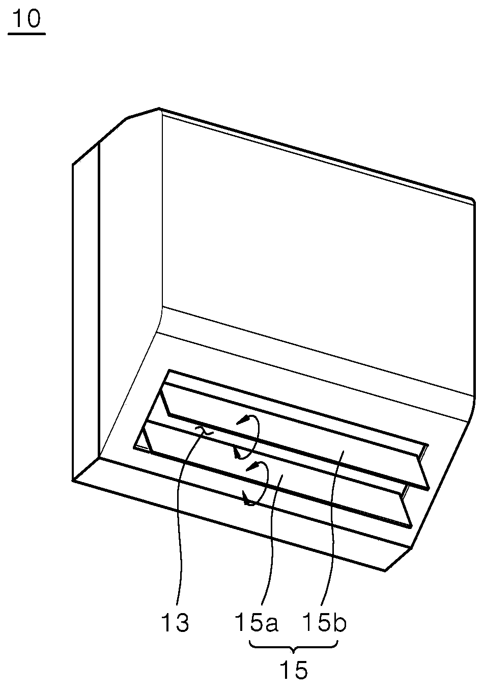
[0005] In addition, according to the prior art, the air blowing direction is adjusted by the multidirectional blades 15a, 15b provided on the discharge port 13, and there is a problem that warm air cannot be sent out at a uniform wind pressure, and noise is generated.
That is, the plurality of directional vanes 15a, 15b provided at the discharge port act as resistance to the wind pressure of the warm air generated by the blower, so not only the blowing wind pressure is affected, but also there is a problem of excessive noise generation.
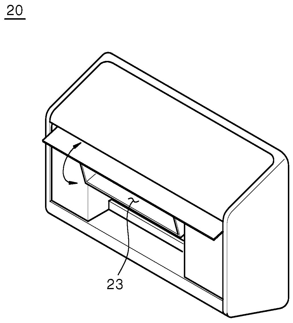
[0006] In addition, according to figure 2 In the prior art shown, in order to change the air blowing direction, there is a situation in which the discharge port 23 is rotated in the up and down direction in the dryer 20 of the prior art, and in this case, there is a problem that it cannot meet the requirements of keeping the air in the bathroom. A matter of user preference for a static and quiet state

Method used


Image

  • Dryer and dryer control method
  • Dryer and dryer control method
  • Dryer and dryer control method

Examples


Embodiment Construction

[0038]The aforementioned objects, features, and advantages will be described in detail later with reference to the accompanying drawings, so that those skilled in the art can easily implement the technical idea of ​​the present invention. In explaining the present invention, when it is considered that the detailed description of known techniques related to the present invention may unnecessarily obscure the gist of the present invention, the detailed description will be omitted. Hereinafter, preferred embodiments of the present invention will be described in detail with reference to the accompanying drawings. The same reference numerals used in the drawings denote the same or similar structural elements.

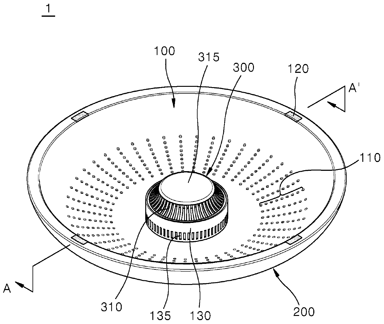
[0039] Below, refer to Figure 3 to Figure 6 A dryer according to an embodiment of the present invention will be described.

[0040] image 3 It is a perspective view of a dryer according to an embodiment of the present invention. Figure 4 It is a side view of the dryer...


PUM


Abstract

The invention provides a dryer and a control method for the dryer. A dryer according to an embodiment of the present invention includes: a front case including a first opening surrounded by a gas guide protruding forward and a plurality of exhaust holes formed around the first opening; a rear case with The front case is combined to include a second opening surrounded by a housing guide protruding rearward, the second opening overlaps the first opening; the fan housing is combined on the first The opening and the second opening are movable forward and backward along the gas guide and the housing guide, and include a blower fan inside the fan housing; and a heater is formed on the fan. On the casing, the wind generated by the blower fan is heated and blown out; the direction of the wind blown out by the heater changes as the fan casing moves forward and backward.

Description

technical field [0001] The present invention relates to a drier and a control method for the drier, and more specifically relates to a drier for drying a space in a bathroom or a user's body and a control method for the drier. Background technique [0002] A dryer is a device that is installed on the wall of a bathroom or toilet to dry the space in the bathroom or to dry the wet body after bathing with warm air. [0003] according to figure 1 As shown in the prior art, the dryer 10 in the prior art may include: directional blades 15, which are rotatably arranged at the outlet 13, and are used to send the warm air generated in the blower in multiple directions. [0004] There is a problem that it is not easy to operate in various modes according to the user's needs in the structure of the conventional dryer as described above. For example, prior art dryers are not easy to control air volume and air direction in various modes when drying a bathroom space and when drying a us...

Claims


Application Information

Patent Timeline
Patent Type & Authority Patents(China)
IPC IPC(8): F24F5/00F24F13/15F24F3/16F24F13/24F24F13/00F24F11/89
CPCF24F5/0003F24F13/00F24F13/15F24F13/24F24F2013/247F24F8/192F24F8/30A47K10/48F24F3/153F24F11/56F24F11/65F24F11/74F24F11/79A61L9/22F26B3/02F26B21/004F26B21/022F26B21/12F26B9/003F26B23/04
Inventor 朴大润金钟锡
Owner LG ELECTRONICS INC
Learn More