
Manufacturing method of corrugated heat exchange tube

A manufacturing method and technology for heat exchange tubes, which are used in tubular elements, heat exchange equipment, lighting and heating equipment, etc., can solve the problems of unsatisfactory surface quality of processing surfaces, irregular shape of heat exchange tubes, and poor mechanical properties. Improve processing quality and heat transfer efficiency, increase processing contact area, and long service life

Active Publication Date: 2018-03-09
NANJING INST OF TECH
View PDF5 Cites 6 Cited by
  • Summary
  • Abstract
  • Description
  • Claims
  • Application Information

AI Technical Summary

Problems solved by technology

[0004] The present invention proposes a manufacturing method for corrugated heat exchange tubes based on problems such as irregular shapes of heat exchange tubes, unsatisfactory surface quality of processed surfaces, low heat exchange efficiency, poor mechanical properties, and short service life caused by existing corrugated tube manufacturing methods. method, by establishing a mathematical model of corrugated pipe processing, using the principle of space envelope to obtain the contact line and the section of the roller shaft, and then applying simulation software to simulate the processing of corrugated pipes, and optimizing the tool parameters and processing by comparing with the ideal size corrugated pipe parameters, and finally use rolling machine to process bellows with good quality and high performance

Method used


Image

  • Manufacturing method of corrugated heat exchange tube
  • Manufacturing method of corrugated heat exchange tube
  • Manufacturing method of corrugated heat exchange tube

Examples


Embodiment Construction

[0043] In order to deepen the understanding of the present invention, the present invention will be further described in detail below with reference to the accompanying drawings and embodiments. The embodiments are only used to explain the present invention and do not limit the protection scope of the present invention.

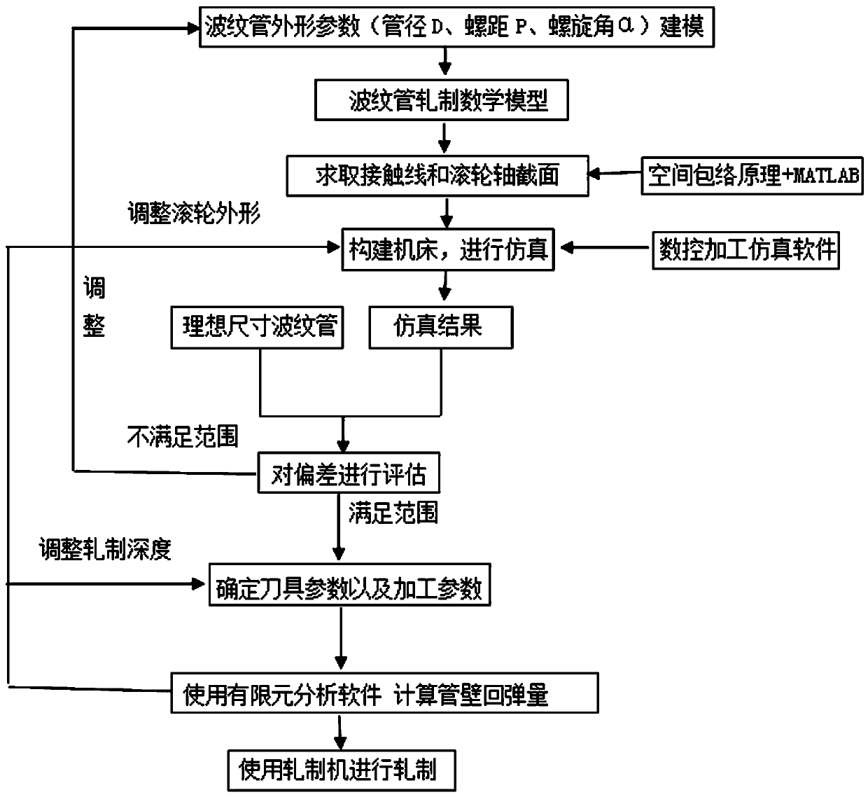
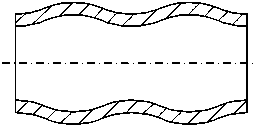
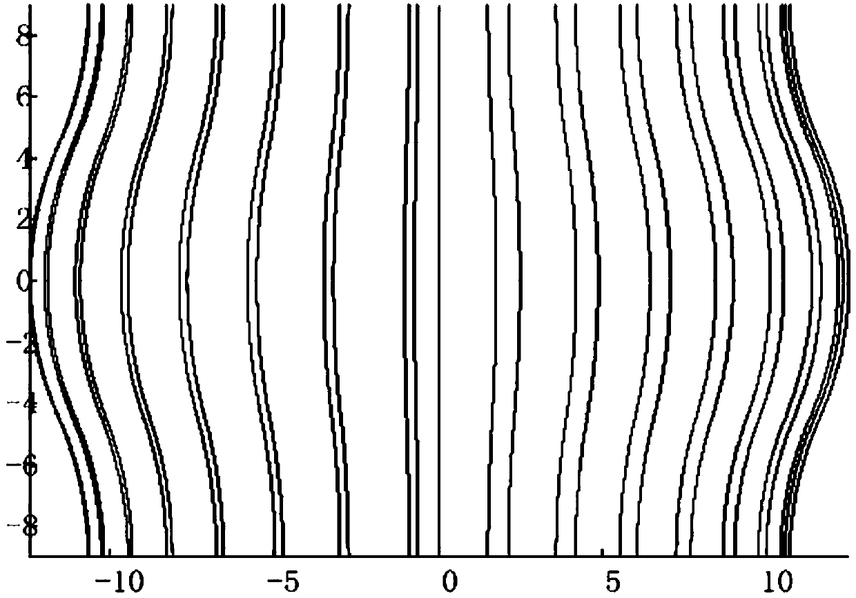
[0044] Such as Figure 1-12 As shown, the present invention is a method for manufacturing a corrugated heat exchange tube. In this embodiment, the revolving surface of the corrugated tube is used as a tool to envelop the spiral surface of the tool. Because the two curved surfaces conform to the conjugate relationship, this solution conforms to For conjugate conditions, first establish the mathematical model of bellows processing, and use the space envelope principle to solve the contact line of the bellows rotary surface and the tool spiral surface, and project to the shaft section of the roller spiral surface, according to the data on the contact line Point cor...


PUM


Abstract

The invention discloses a manufacturing method of a corrugated heat exchange tube. The manufacturing method comprises the following steps of (1), constructing the model of the contour parameter of a corrugated tube; (2), carrying out the section design of a roller wheel by utilizing a spatial envelope principle, and solving a contact line and the axial section of the roller wheel; (3), constructing a machine tool and carrying out simulation by using numerical control processing simulation software; (4), comparing a simulation result with an ideal-size corrugated tube, and estimating a deviation; (5), determining a cutter parameter and a processing parameter; (6), simulating by using finite element analysis software and calculating the resilient amount of a tube wall; (7), processing by using a rolling machine. According to the method, through establishing a mathematic model for processing the corrugated tube, the contact line and the axial section of the roller wheel are solved by utilizing the spatial envelope principle; further, the corrugated tube is processed in a simulation manner by applying the simulation software; through the compassion with the ideal-size corrugated tube,the tool parameter and the processing parameter are optimized and finally, the corrugated tube which is good in quality and high in performance is finally processed by using the rolling machine.

Description

Technical field [0001] The invention relates to a process method for processing the surface of a pipe fitting, in particular to a manufacturing method for processing the surface of a corrugated heat exchange tube. Background technique [0002] The heat exchanger is a heat exchange device that transfers part of the heat of the hot fluid to the cold fluid, so that the fluid temperature reaches the specified index of the process flow. The heat exchange tube is the core component of the heat exchanger. At present, domestic and foreign has been committed to designing and developing various types High-performance heat exchange tubes, and corrugated heat exchange tubes are a common type of highly efficient enhanced heat exchange tubes. How to improve the manufacturing quality and performance of corrugated heat exchange tubes has always been the focus of research in the field of heat exchangers. [0003] At present, the traditional corrugated heat exchange tube is processed into a corrugat...

Claims


Application Information

Patent Timeline
Patent Type & Authority Applications(China)
IPC IPC(8): G06F17/50F28F1/06
CPCF28F1/06G06F30/23
Inventor 朱大胜李修珍杨会超张文全李果王科伟季尧杰
Owner NANJING INST OF TECH
Learn More