Austenitic stainless steel continuous casting method for improving surface defects
A technology of austenitic and stainless steel, applied in the field of continuous casting of austenitic stainless steel, can solve the problems of inability to judge, the actual yield reduces grinding costs, etc., and achieves the effect of improving defects and reducing black belt defects.
- Summary
- Abstract
- Description
- Claims
- Application Information
AI Technical Summary
Problems solved by technology
Method used
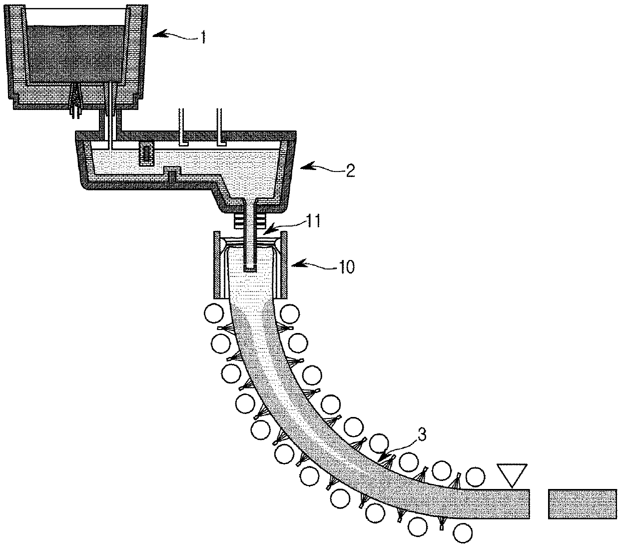
Image


Examples
Embodiment 1-6
[0080] During the continuous casting of austenitic stainless steel, the continuous casting slabs were manufactured according to the conditions in the following Table 1, and the slag and slag lumps in the mold were confirmed during continuous casting, and the presence of defects on the surface of the slabs was confirmed visually, and the display in Table 2 below.
[0081] 【Table 1】
[0082]
[0083]
[0084] 【Table 2】
[0085]
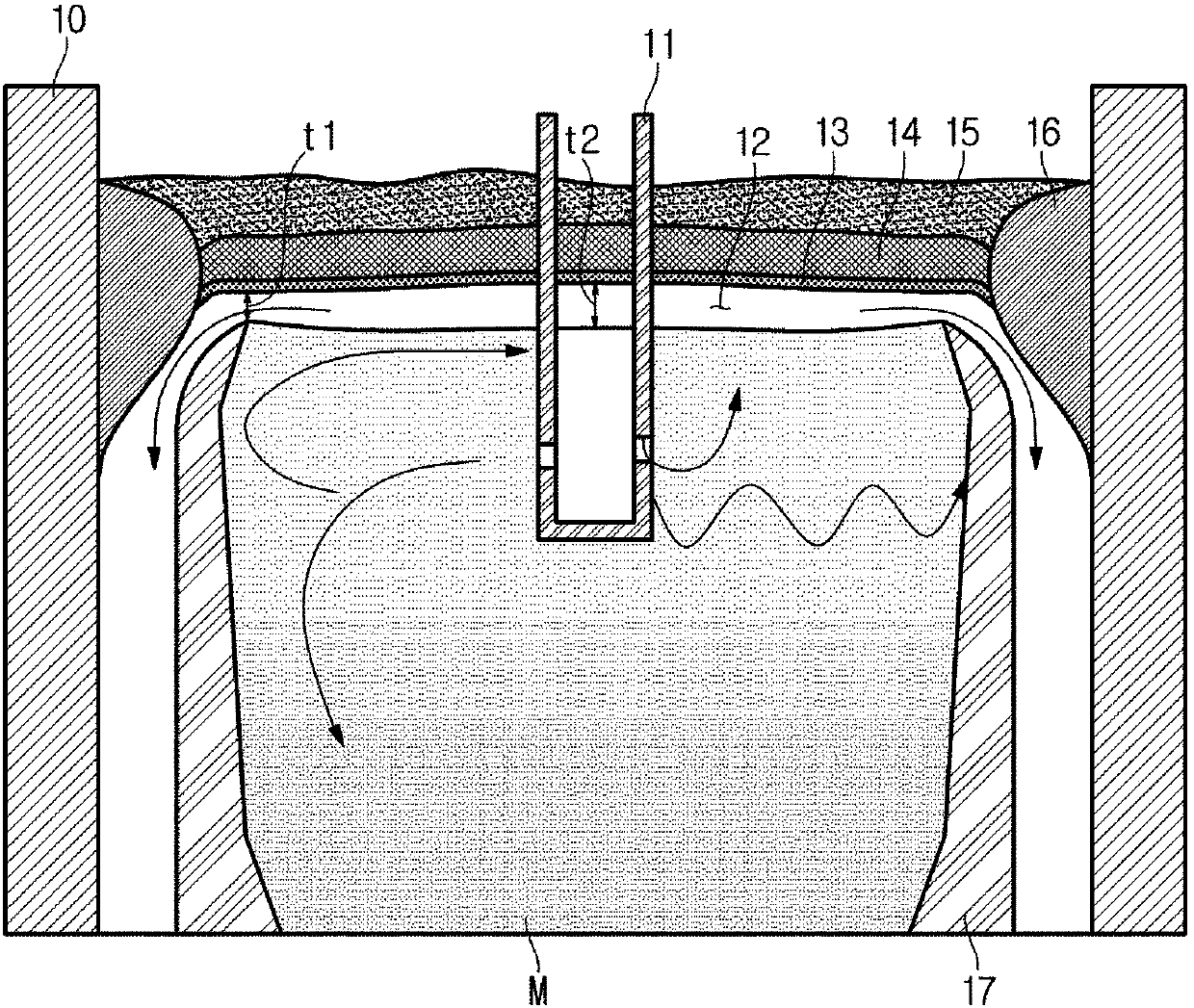
[0086] Referring to Table 1 and Table 2, when the casting temperature superheat ΔT is in the range of 20 to 40°, and the discharge angle of the submerged nozzle is from 0° to 15° downward, the thickness of the center and edge of the slag layer The difference is -3 to 6mm, less than 10mm, and when the width ratio of the slag block is properly controlled below 110%, there is no abnormal structure on the surface layer, and no black band defect occurs on the hot-rolled product.
[0087] It can be judged that in the section where the degree of super...
Embodiment 7-9
[0100] When continuous casting of austenitic stainless steel, according to the conditions in the following Table 3, set the area where the mold powder is not put in, set the superheat of the casting temperature to 50°C, and set the discharge angle of the submerged nozzle to 0°, so that Continuous casting slabs were produced, and whether defects occurred on the surface of the slabs was judged with the naked eye, and the results are shown in Table 3.
[0101] 【table 3】
[0102]
[0103] As shown in Comparative Examples 10 and 11, it can be seen that the non-introduced area of mold flux is 10% or less. If it becomes too small, a sufficient slag layer cannot be secured, and slab surface defects occur. As shown in Comparative Example 12, it can be seen that protection If the area where the slag is not injected is too large, the meniscus surface layer of molten steel is excessively cooled, and slab surface layer defects occur.
PUM
 Abstract
Description
Claims
Application Information
 - R&D Engineer
- R&D Manager
- IP Professional
- Industry Leading Data Capabilities
- Powerful AI technology
- Patent DNA Extraction
Browse by: Latest US Patents, China's latest patents, Technical Efficacy Thesaurus, Application Domain, Technology Topic.
© 2024 PatSnap. All rights reserved.Legal|Privacy policy|Modern Slavery Act Transparency Statement|Sitemap