Special tool fixture for vertical type combined machining center

A composite machining center and fixture technology, applied in the direction of manufacturing tools, metal processing equipment, metal processing machinery parts, etc., can solve the conditions of processing requirements, inability to process, affect processing efficiency and other problems, to expand the processing range, The effect of reducing repeated clamping and improving machining accuracy

Pending Publication Date: 2018-03-13
大连诺酉工程技术有限公司
View PDF0 Cites 5 Cited by
  • Summary
  • Abstract
  • Description
  • Claims
  • Application Information

AI Technical Summary

Problems solved by technology

[0002] At present, as far as the field of mechanical processing is concerned, in most cases the supporting facilities of the machine tool itself are very limited. Under the premise of no special requirements, the corresponding tooling matched with the machine tool is also the most basic, so in the process of processing, it can meet the processing needs. conditions are thus limited
In terms of efficiency, some parts need repeated clamping and processing to complete, and some parts cannot be processed at all because they exceed the processing range; in terms of accuracy, errors caused by repeated clamping are undoubtedly to be avoided to ensure processing accuracy , the processing of multiple steps s

Method used


Image

  • Special tool fixture for vertical type combined machining center
  • Special tool fixture for vertical type combined machining center
  • Special tool fixture for vertical type combined machining center

Examples


example 1

[0051] Machine tool used: Pietro Carnaghi (Pietro Carnaghi) 1.6m vertical compound turning and milling machining center.

[0052] Scope of application: medium and large parts with a slewing diameter > 1600m, a clamping height > 170mm, and asymmetrical clamping types.

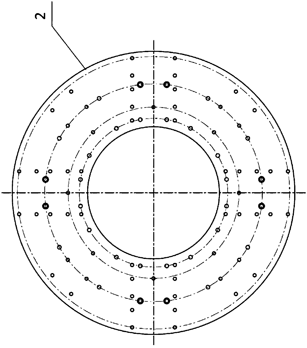
[0053] Processed parts: fixed planet carrier. Fixed planet carrier structure such as Figure 3a and 3b As shown, the rotation diameter of the fixed planet carrier is 1760mm, and the minimum clamping rotation diameter is 1920mm, which is far beyond the working range of the workbench of 1600mm; The connection beam at the place), it is impossible to achieve symmetrical clamping; the coaxiality and position of the parts are required to be high, and there are many processing positions for the hole type, so it is not suitable for repeated clamping.

[0054] Tooling process for fixing the planet carrier:

[0055] (1) Clean the rotary table 9 of the vertical machining center, remove the iron filings on the surface a...

Embodiment 2

[0068] Machine tool used: Pietro Carnaghi (Pietro Carnaghi) 1.6m vertical compound turning and milling machining center.

[0069] Scope of application: medium and large parts with a slewing diameter > 1600m, a clamping height > 170mm, and asymmetrical clamping types.

[0070] Machining parts: input planet carrier. Fixed planet carrier structure such as Figure 6a and 6b As shown, the height of the input planet carrier is relatively high, so the clamping height must meet the processing force requirements and should not be too low; Figure 6a As shown, the upper side of the input planet carrier connection (the lower side of the input planet carrier, the far end of the planetary hole) has a non-rotating design, and the theoretical clamping position is the casting surface, which cannot achieve symmetrical clamping, and cannot be used as a secondary clamping The benchmark; the coaxiality and position of the parts have higher requirements, such as Figure 6b The flange faces on ...


PUM


Abstract

The invention relates to the technical field of vertical composite turning and milling, in particular to a special fixture for a vertical composite machining center. The tooling fixture includes a rotary tray 2, a claw high support 3 and several bolts and nuts fixing parts, as well as ring pad iron, a central fixed plate of a ring structure, a contour pad, and a pressure plate. The diameter of the circle is smaller than the rotary limit range of the rotary table of the vertical compound machining center, and the high-position support of the jaws is a weldment, which is used to increase the clamping position of the chuck jaws. The present invention can maximize the processing range of the workbench of the vertical composite machining center without affecting the machining accuracy; moreover, it can simulate the clamping method of the workbench, so that the clamping method is not only limited to the modes that the workbench itself can provide, but also What matters is diversity. The invention can be widely popularized in the fields of machine tool processing and the like.

Description

technical field [0001] The invention relates to the technical field of vertical composite turning and milling, in particular to a special fixture for a vertical composite machining center. Background technique [0002] At present, as far as the field of mechanical processing is concerned, in most cases the supporting facilities of the machine tool itself are very limited. Under the premise of no special requirements, the corresponding tooling matched with the machine tool is also the most basic, so in the process of processing, it can meet the processing needs. conditions are thus limited. In terms of efficiency, some parts need repeated clamping and processing to complete, and some parts cannot be processed at all because they exceed the processing range; in terms of accuracy, errors caused by repeated clamping are undoubtedly to be avoided to ensure processing accuracy , the processing of multiple steps should be completed with the least number of clamping times, the purp...

Claims


Application Information

Patent Timeline
IPC IPC(8): B23Q3/06
CPCB23Q3/062
Inventor 刘易侯鹏刘静
Owner 大连诺酉工程技术有限公司
Why Eureka
Try Eureka