Storing device for sewing workshop
A technology for production workshops and storage devices, which is applied to sewing equipment, sewing machine components, clothing piece collection devices, etc., which can solve the problems of inconvenient disassembly and mobile operation, large tank body, etc., and achieve easy disassembly, mobile operation and operation The effect of convenience and simple structure
- Summary
- Abstract
- Description
- Claims
- Application Information
AI Technical Summary
Problems solved by technology
Method used
Image
Examples
Embodiment 1
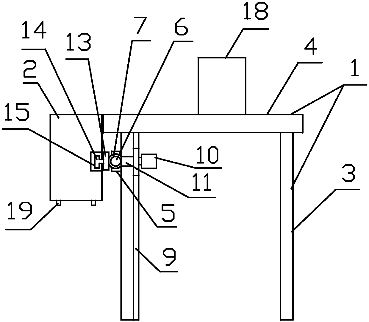
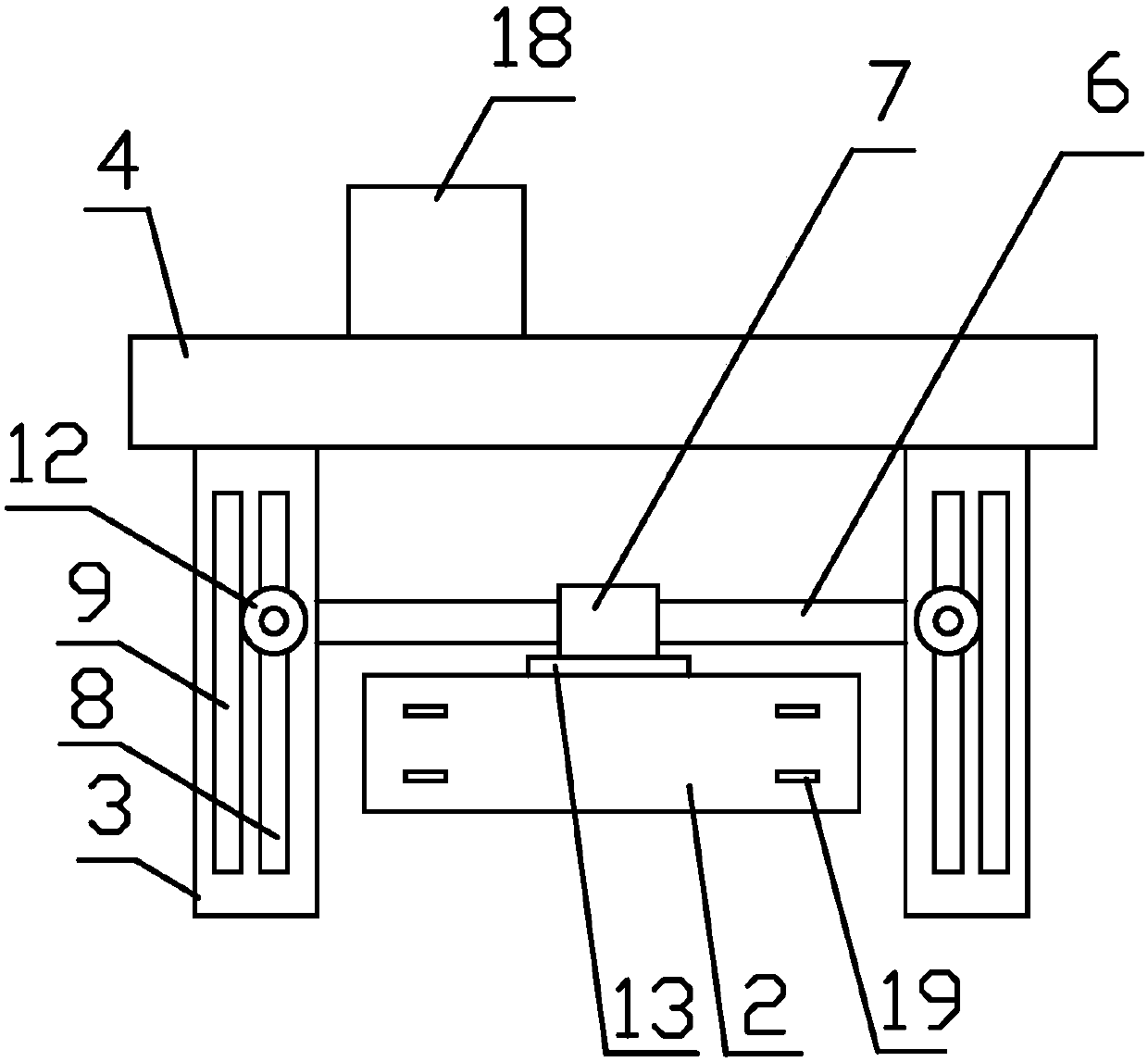
[0028] like Figure 1~3 As shown, the storage device for the sewing production workshop of the present invention includes a frame 1 and a storage tank 2, the frame 1 includes four legs 3 and a workbench 4, and two adjacent legs 3 are provided with Slider 5, said slider 5 slides along the axial direction of leg 3; also includes fixed rod 6, the two ends of the long axis direction of said fixed rod 6 are fixed on two adjacent legs 3 On the slider 5; the middle part of the fixed rod 6 is covered with a rotating shaft sleeve 7, and the storage tank 2 is detachably connected and fixed on the rotating shaft sleeve 7, and rotates with the rotating shaft sleeve 7 with the fixed rod 6 as the axis.
Embodiment 2
[0030] Further on the basis of Embodiment 1, a chute 8 and a rack 9 are provided on the two adjacent legs 3, the extension direction of the chute 8, the long axis direction of the rack 9 and the direction of the leg 3 The long axis directions of the shafts are all parallel; also include a motor 10, a rotating shaft 11, and a gear 12 meshed with the rack 9, the gear 9 is fixed on the rotating shaft 11, and one axial end of the rotating shaft 11 is driven to rotate by the motor 10, and the other One end passes through the chute 8 , and the free end of the chute 8 is fixedly connected with the slider 5 through a universal joint. The end surface of the slider 5 connected to the rotating shaft 11 is provided with a wear-reducing sheet, and the slider 5 is in contact with the leg 3 through the wear-reducing sheet.
Embodiment 3
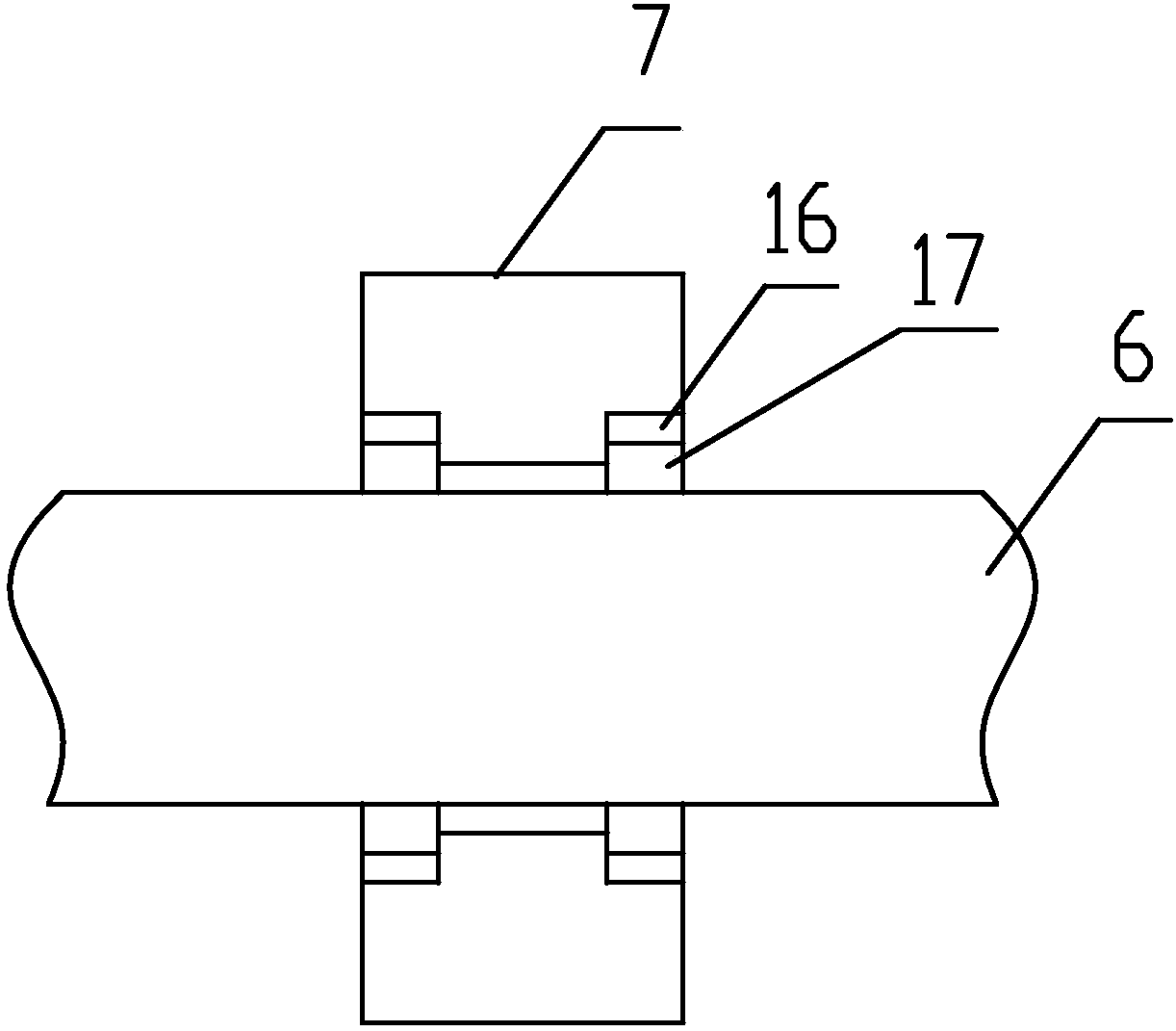
[0032] Further on the basis of Embodiment 2, a fixed plate 13 is provided on the rotating shaft sleeve 7, and a limit block 14 is protruded from the surface of the fixed plate 13. There is a limit groove 15 adapted to the limit block 14, and the extension direction of the limit groove 15 is perpendicular to the axial direction of the leg 3; The matching connection realizes detachable connection and is fixed on the fixed plate 13. The limiting block 13 has a T-shaped structure, and the limiting groove 14 has a C-shaped structure. The axial ends of the shaft sleeve 7 are protrudingly provided with limit latches 16 on the inner wall, and the upper outer wall of the fixed rod 6 is provided with two fixed latches 17 meshing with the limit latches 16 along the circumferential ring. ; The limiting latch 16 and the fixed latch 17 are both made of elastic aluminum.
PUM
 Abstract
Description
Claims
Application Information
 - R&D
- Intellectual Property
- Life Sciences
- Materials
- Tech Scout
- Unparalleled Data Quality
- Higher Quality Content
- 60% Fewer Hallucinations
Browse by: Latest US Patents, China's latest patents, Technical Efficacy Thesaurus, Application Domain, Technology Topic, Popular Technical Reports.
© 2025 PatSnap. All rights reserved.Legal|Privacy policy|Modern Slavery Act Transparency Statement|Sitemap|About US| Contact US: help@patsnap.com


