
New load-sensitive balance valve

A technology of load-sensitive and balanced valves, which is applied in the direction of fluid pressure actuators, servo motor components, mechanical equipment, etc., can solve the problems of large leakage and poor sealing performance, and achieve small pressure loss, stable load movement, and boom motion smoothing effect

Inactive Publication Date: 2018-03-13
宋珊珊
View PDF0 Cites 2 Cited by
  • Summary
  • Abstract
  • Description
  • Claims
  • Application Information

AI Technical Summary

Problems solved by technology

[0004] In order to overcome the poor sealing performance of the existing load-sensing balancing valve and the large leakage during operation, the present invention provides a new type of load-sensing balancing valve, which has good sealing performance and improves the valve Body sealing performance; at the same time, the flow rate is stable, ensuring the smooth movement of the boom

Method used


Image

  • New load-sensitive balance valve
  • New load-sensitive balance valve

Examples


Embodiment Construction

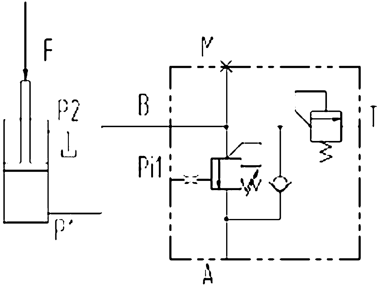
[0012] preferred, such as figure 1 As shown, A is the oil inlet port of the forward channel, B is the load port connected with the hydraulic cylinder, Pil is the pilot port, T is the external drain port, and M is the pressure measuring port. Different from the traditional balance valve, the balance valve introduces the load signal into the side where the spring of the balance valve is located, and the elastic force generated by the spring and the feedback force generated by the load signal act together on the side of the spool to balance the pilot control force and adjust the flow area of ​​the balance valve. In this way, the back pressure is adapted to the load to ensure the smooth movement of the load.

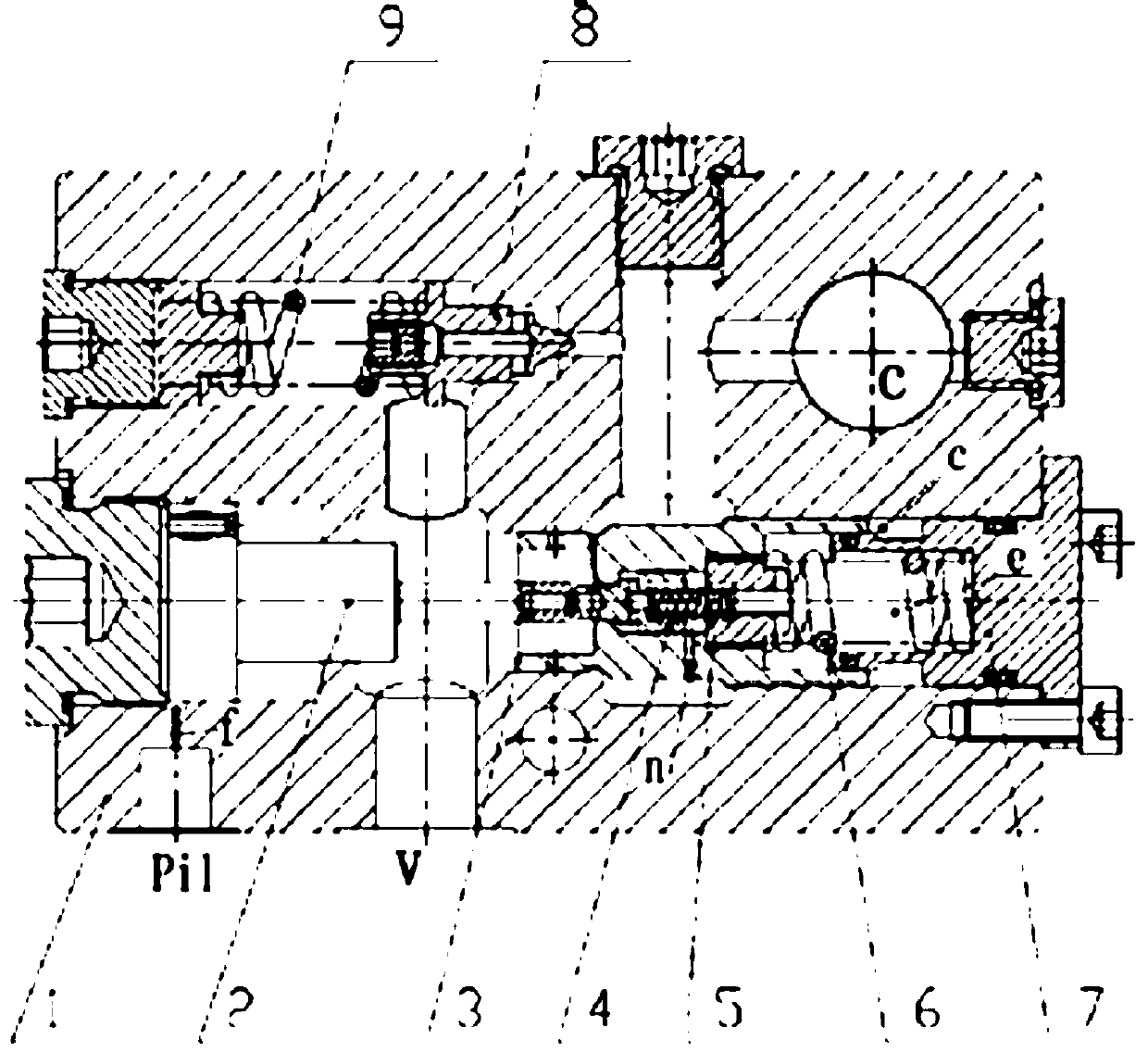
[0013] preferred, such as figure 2 As shown, the balance valve is composed of valve body 1, pilot piston 2, main balance spool 3, small pilot spool 4, overflow spool 8 and other parts and components. The balance valve end cover 7 isolates the load chamber c from the sprin...


PUM


Abstract

A novel load sensitive balance valve is composed of a valve body, a control piston, a main balance spool and a pilot spool spring. The new balance valve is mainly composed of a one-way function component, an overflow function component, and a throttling spool component that plays the main role of flow control; When it is blocked, the high pressure in the load chamber acts on the right side of the main balance spool to greatly reduce the action area, forming a feedback signal; the force of the load acting on the balance spool will change with the change of the load, thereby changing the balance The flow area of ​​the valve maintains the flow stability and ensures the smooth movement of the boom; according to the oil flow direction, when the balance valve is in front of the hydraulic cylinder, the oil enters from the oil inlet and flows out through the one-way valve flow channel in the valve body. The pressure loss is small.

Description

Technical field [0001] The invention relates to a novel load sensitive balance valve, which is especially applied to electromechanical products. Background technique [0002] With the in-depth application of information technology, the transformation of industry, the rapid advancement of urbanization, the assembly manufacturing industry from large to strong, and the market demand formed by human beings' deep development of ocean depths and land depths, fluid power The industry has developed rapidly in the past ten years. According to the statistics of the my country Liquid and Gas Seal Industry Association, the total output value of the pneumatic, hydraulic, hydraulic, and seal industries in 2011 increased by 11.85 times compared with 2000, while the hydraulic industry increased by 11.3 times. In 2013, my country's fluid power industry accounted for a substantial increase in the global market share, of which the hydraulic market reached 27%, and the pneumatic market reached...

Claims


Application Information

Patent Timeline
Patent Type & Authority Applications(China)
IPC IPC(8): F15B13/042
CPCF15B13/0426
Inventor 宋珊珊
Owner 宋珊珊
Learn More