Air source heat pump system and control method thereof

An air source heat pump and control method technology, applied in the field of heat pumps, can solve the problems of inability to evaporate liquid working medium, liquid in the suction of the compressor, and inability to continue heating, etc., to achieve the effects of enhanced condensation effect, increased energy, and faster time

Pending Publication Date: 2018-03-13
GREE ELECTRIC APPLIANCES INC
View PDF5 Cites 3 Cited by
  • Summary
  • Abstract
  • Description
  • Claims
  • Application Information

AI Technical Summary

Problems solved by technology

However, there are few studies on self-cascading air-source heat pump defrosting at present. When the existing self-cascading air-source heat pump cycle is heating in a low-temperature and high-humidity environment, the evaporator frosting phenomenon is more serious.
When the frost on the evaporator is thick, it will lead to poor heating effect. If the traditional compressor exhaust is directly introduced into the evaporator for direct hot gas bypass defrosting, the defrosting energy used only comes from the power consumption of the compressor. As a result, the defrosting speed is slow, and the liquid working medium produced by the evaporator cannot be evaporated after the hot gas defrosting, so it is easy to cause the compressor to absorb liquid during the defrosting process and cannot continue heating.

Method used


Image

  • Air source heat pump system and control method thereof

Examples


Embodiment Construction

[0023] The present invention will be described in detail below with reference to the accompanying drawings and examples.

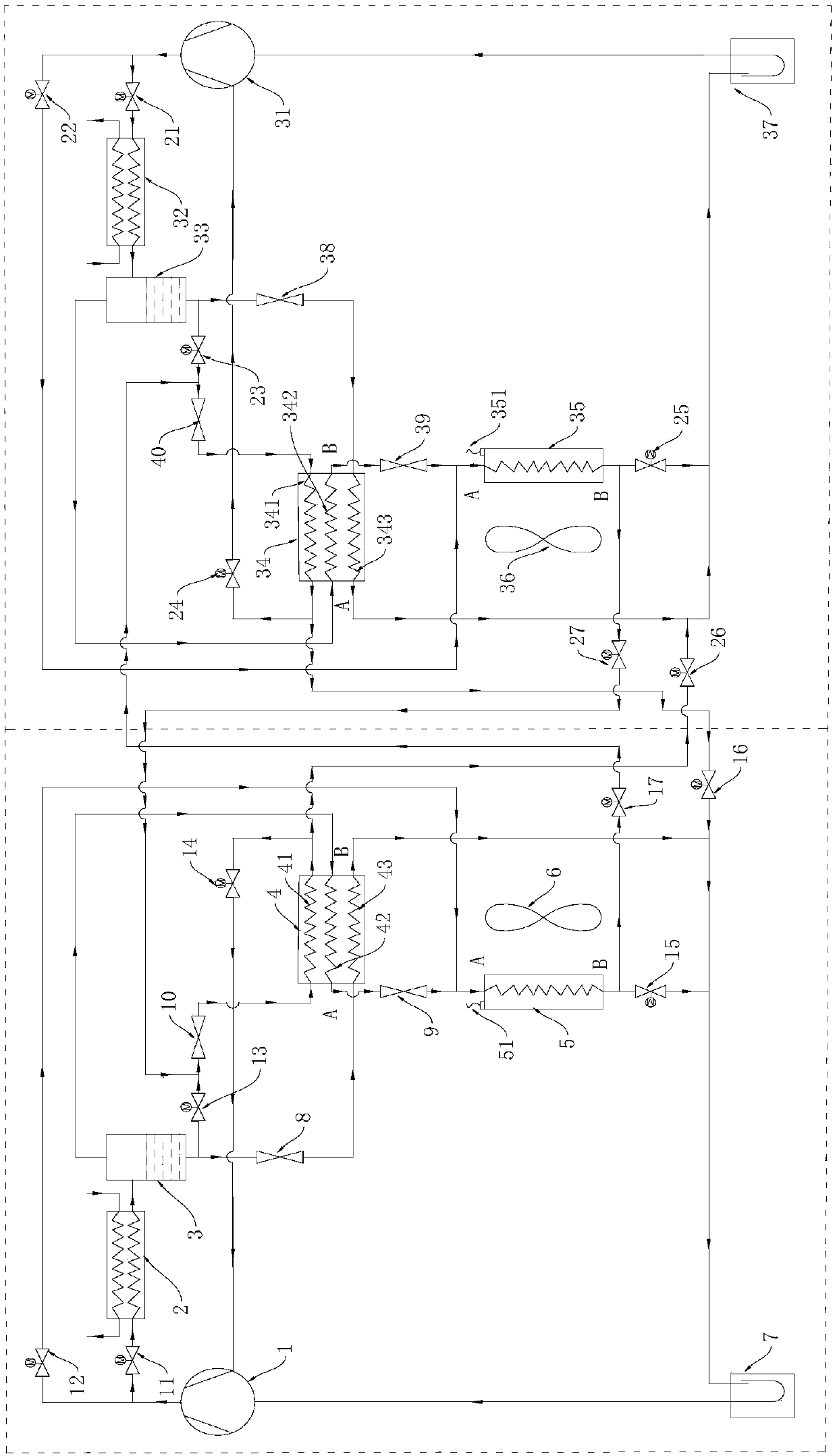
[0024] Such as figure 1As shown, according to the system diagram of the air source heat pump system of the present invention, an air source heat pump system is proposed in an embodiment of the present invention, and the air source heat pump system may include: a first subsystem and a second subsystem; A subsystem includes: a first compressor 1, a first condenser 2, a first gas-liquid separator 3, a first heat exchanger 4, a first throttle valve 8, a second throttle valve 9, and a first evaporator 5; The second subsystem includes: the second compressor 31, the second condenser 32, the second gas-liquid separator 33, the second heat exchanger 34, the fourth throttle valve 38, the fifth throttle valve 39, the second Six throttling valves 40, the second evaporator 35; the first condenser 2 can communicate with the outlet end of the first compressor 1, the inl...


PUM


Abstract

The invention provides an air source heat pump system and a control method thereof, and relates to the technical field of heat pumps. The air source heat pump system comprises a first subsystem and asecond subsystem; the first subsystem comprises a first compressor, a first condenser, a first gas-liquid separator, a first heat exchanger, a first throttle valve, a second throttle valve and a firstevaporator; and the second subsystem comprises a second compressor, a second condenser, a second gas-liquid separator, a second heat exchanger, a fourth throttle valve, a fifth throttle valve, a sixth throttle valve and a second evaporator. The air source heat pump system and the control method thereof can simultaneously conduct defrosting on the first evaporator in the case of continuous heating.

Description

technical field [0001] The invention relates to the technical field of heat pumps, in particular to an air source heat pump system and a control method thereof. Background technique [0002] The self-cascading air source heat pump cycle can achieve a high compression ratio, and can operate in a working environment with a large temperature difference, especially at a low ambient temperature, it can still provide hot water above 65°C, which can be widely used in people's production or Domestic heating or water. However, there are few studies on self-cascading air-source heat pump defrosting at present. When the existing self-cascading air-source heat pump cycle is heating in a low-temperature and high-humidity environment, the evaporator frosting phenomenon is more serious. When the frost on the evaporator is thick, it will lead to poor heating effect. If the traditional compressor exhaust is directly introduced into the evaporator for direct hot gas bypass defrosting, the de...

Claims


Application Information

Patent Timeline
IPC IPC(8): F25B30/02F25B41/04F25B47/02F25B49/02F25B41/20
CPCF25B30/02F25B47/022F25B49/02F25B2347/02F25B41/20
Inventor 魏峰孙思刘金喜张恩泉贺秋李华本代园温祖恒
Owner GREE ELECTRIC APPLIANCES INC
Why Eureka
Try Eureka