
Device for measuring air intake flow of engine

A technology of air intake flow and measurement devices, which is applied in the direction of measurement devices, engine testing, machine/structural component testing, etc., can solve problems such as large errors, high costs, and restrictions on pipeline layout, and achieve small impact and fast response Fast, small pressure loss effect

Inactive Publication Date: 2018-03-13
武汉东测科技有限责任公司
View PDF0 Cites 0 Cited by
  • Summary
  • Abstract
  • Description
  • Claims
  • Application Information

AI Technical Summary

Problems solved by technology

[0005] The utility model is mainly to solve the problems of large error, high cost and limitation by pipeline arrangement existing in the existing engine air intake flow measurement

Method used


Image

  • Device for measuring air intake flow of engine
  • Device for measuring air intake flow of engine

Examples


Embodiment Construction

[0015] Below in conjunction with accompanying drawing, the utility model is further described:

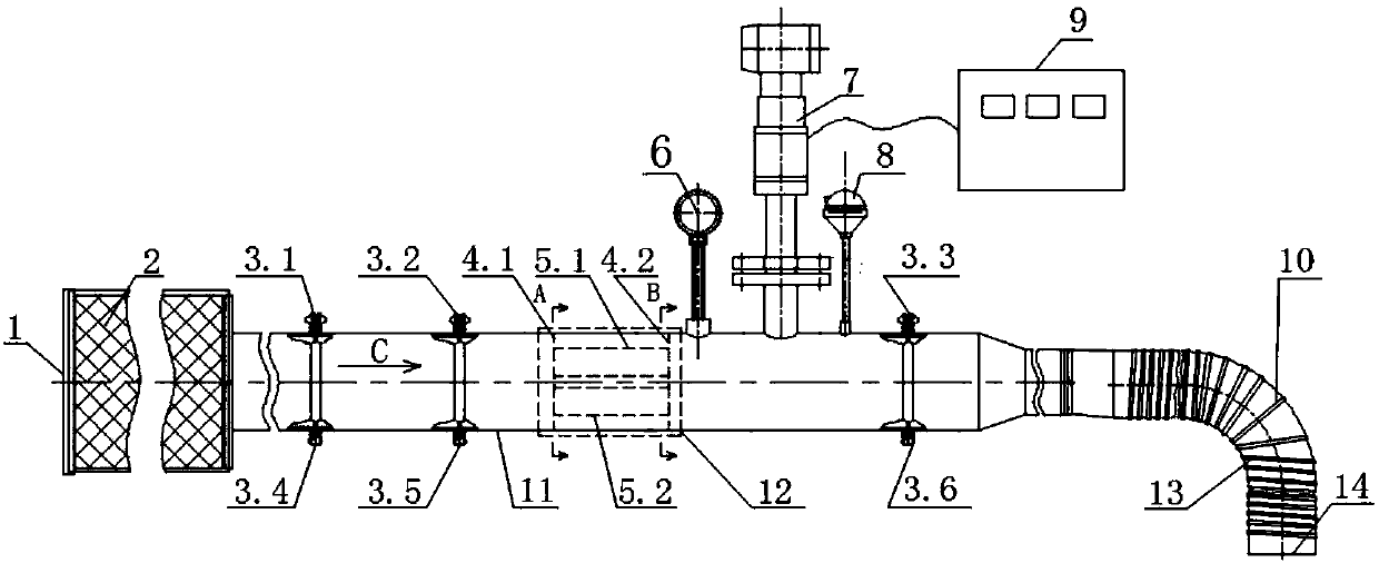
[0016] Such as figure 1 As shown, an engine air intake flow measurement device includes an air inlet 1, a pressure transmitter 6, an air flow meter 7, a temperature sensor 8, an air pipeline 11, and an air connection port 14, which is characterized in that the air pipeline Air filter 2 is housed at the air inlet 1 place of 11 one ends, is used for preventing intake air duct 11 from being polluted.

[0017] The air connection port 14 of the other end of the air pipeline 11 is equipped with a steel wire hose 10 that is convenient to be connected with the engine air inlet. The steel wire hose 10 is embedded with a steel wire 13, which can prevent the unstable air pressure in the pipe from deforming the hose.

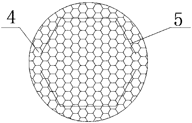
[0018] The air pipeline 11 is also equipped with a honeycomb rectifier 12, which can balance the internal pressure, reduce errors, and reduce the length of straight pipe sectio...


PUM


Abstract

The invention is an engine air intake flow measuring device, which is characterized in that an air filter is installed at the air inlet at one end of the air pipeline, and a steel wire hose is equipped at the air connection at the other end of the air pipeline, and the inside of the air pipeline is A honeycomb rectifier is also installed, and the outer surface of the air pipeline between the honeycomb rectifier and the steel wire hose is sequentially installed with a pressure sensor, an air flow meter and a temperature sensor, and an intelligent flow totalizer is installed on one side of the air flow meter . After the pipeline is reduced in diameter, it is connected to the air inlet of the engine through a steel wire hose, which can effectively save materials and experimental space, and has a wide range of applications, high measurement accuracy, good stability, and small pressure loss.

Description

technical field [0001] The utility model relates to the technical field related to engine testing, in particular to an engine air intake flow measuring device. Background technique [0002] The measurement of the intake flow of the engine is very important. The accuracy of the flow rate measured by the flowmeter is not only related to the accuracy of the flowmeter itself, but also related to its installation position. The ideal installation position of the flowmeter is that the flow state of the upstream and downstream fluids is single-phase Steady flow, so that the influence of local resistance pipe fittings upstream and downstream of the flowmeter on the fluid flow state does not directly affect the measurement accuracy of the flowmeter. The flowmeter fluid must form a typical flow velocity distribution (laminar flow velocity distribution and turbulent flow velocity distribution) in a circular pipe in order to use a mature mathematical model for calculation and accurate me...

Claims


Application Information

Patent Timeline
Patent Type & Authority Applications(China)
IPC IPC(8): G01M15/02
CPCG01M15/02
Inventor 张希
Owner 武汉东测科技有限责任公司
Learn More