
Rotary chute type division device and coal sample preparation device

The technology of a splitter and a slide pipe is applied in the field of coal sample preparation, which can solve problems such as inability to guarantee coal flow, blockage of the splitting port, cross-contamination, etc., so as to improve the efficiency of coal sample preparation, improve the precision of splitting and splitting high precision effect

Active Publication Date: 2018-03-13
长沙开元仪器有限公司
View PDF8 Cites 2 Cited by
  • Summary
  • Abstract
  • Description
  • Claims
  • Application Information

AI Technical Summary

Problems solved by technology

[0005] On the one hand, due to the effect of centrifugal force, the coal flow entering the shrinkage opening cannot ensure that the flow rate of the coal flow entering each shrinkage divider is the same, and the coal sample may also hit the circumferential wall, resulting in coal of different particle sizes entering the shrinkage opening. Naturally, within the same time period, there may be differences in the quality of the coal flow entering each shrinkage port, which affects the sampling quality and particle size distribution of the analyzed coal samples, and it is difficult to guarantee the precision of the shrinkage
[0006] On the other hand, when the coal flow entering the shrinkage port has a large amount of moisture or a large coal flow block, the moisture adaptability of the shrinker itself is poor, resulting in blockage of the shrinkage port, and even causing residual coal, coal leakage and cross-contamination The problem of equal shrinkage makes the shrinkage uneven and the precision of the shrinkage is poor
[0007] Therefore, the divider in the prior art has the problem of poor division precision
How to solve the problem of poor precision of reduction and division is a technical problem to be solved by those skilled in the art

Method used


Image

  • Rotary chute type division device and coal sample preparation device
  • Rotary chute type division device and coal sample preparation device
  • Rotary chute type division device and coal sample preparation device

Examples


Embodiment Construction

[0031] The following will clearly and completely describe the technical solutions in the embodiments of the present invention with reference to the accompanying drawings in the embodiments of the present invention. Obviously, the described embodiments are only some, not all, embodiments of the present invention. Based on the embodiments of the present invention, all other embodiments obtained by persons of ordinary skill in the art without making creative efforts belong to the protection scope of the present invention.

[0032] In order to enable those skilled in the art to better understand the solution of the present invention, the present invention will be further described in detail below in conjunction with the accompanying drawings and specific embodiments.

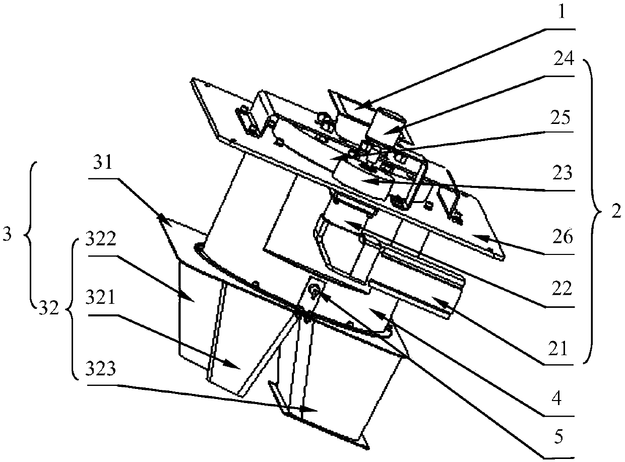
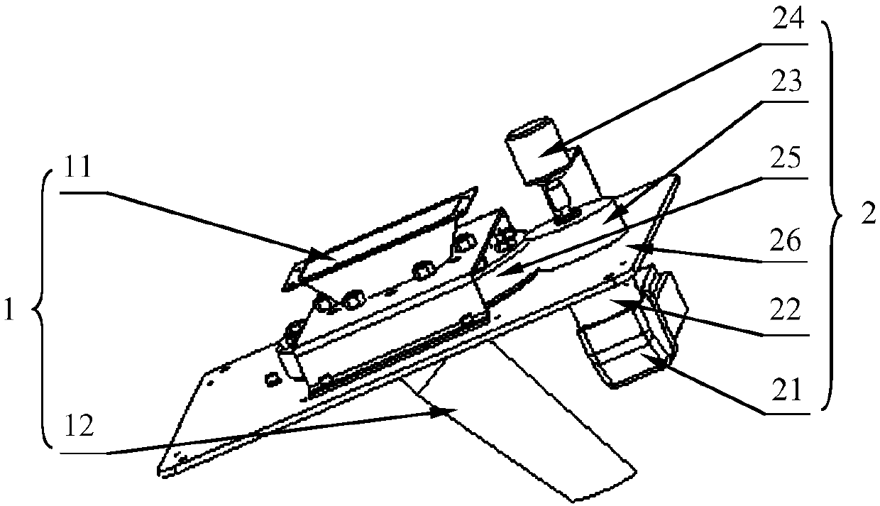
[0033] Please refer to figure 1 , figure 1 It is a structural schematic diagram of a rotary chute type shrinker provided by a specific embodiment of the present invention.

[0034] The embodiment of the present in...


PUM


Abstract

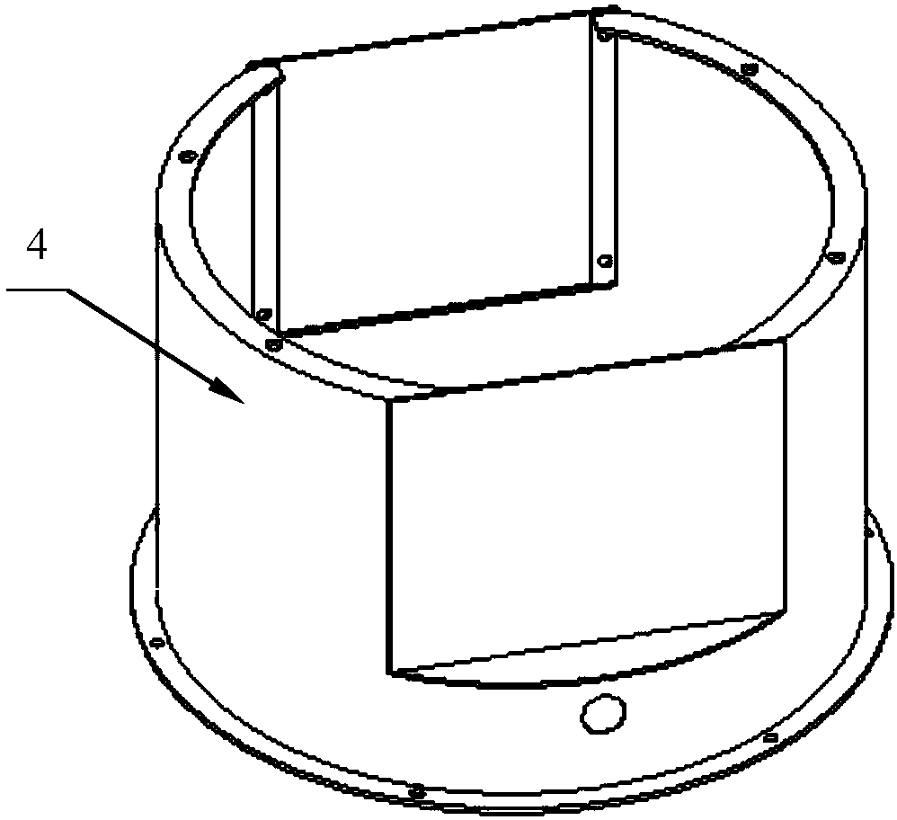
The application discloses a rotary chute type division device, which comprises a chute component in which a coal flow is flowed, a driving control device, and a slotting discharging hopper; the driving control device is connected with the chute component and used for driving and controlling the chute component to perform rotary movement, and the slotting discharging hopper is located at the tail end of the chute component and used for cutting the coal flow from the chute component; the slotting discharging hopper is provided with a discharging hopper with different sampling angles. For the uniform coal flow passes through the upper part of the slotting discharging hopper by exact time ratio, several parts of coal samples with different masses and fixed quality are acquired from the slotting discharging hopper; the rotary chute type division device is good for improving the division precision. The application further discloses a coal sampling preparation device; for the coal sample canbe acquired at fixed quality, the rotary chute type division device is good for improving the preparation efficiency of the coal sample.

Description

technical field [0001] The invention relates to the field of coal sample preparation, in particular to a rotary slide tube type shrinker. The invention also relates to a coal sample preparation device. Background technique [0002] As an important strategic energy source, coal is widely used in power generation, heating, chemical industry and so on. However, since the composition of coal varies widely from region to region, in order to be able to accurately control the amount of coal used and where it is used, it is usually necessary to conduct further composition inspections on the mined coal. Naturally, coal sample preparation equipment is inseparable from the inspection process . Generally, coal sample preparation equipment includes crushers, shrinkers, mixers, screening equipment, drying equipment, etc., to prepare collected coal samples into coal samples for analysis that can represent the characteristics of the original coal samples. Therefore, coal sample preparati...

Claims


Application Information

Patent Timeline
IPC IPC(8): G01N1/28
CPCG01N1/286
Inventor 罗建文李朝弟付杰勤周磊肖鹏飞汤良宇郭晓明黄锋
Owner 长沙开元仪器有限公司
Learn More