
Calculation method of joint action of load and structure under water pressure in composite lining of shield tunnel

A composite lining and co-action technology, applied in tunnel lining, calculation, wellbore lining, etc., can solve problems such as waste, lack of recognized and reliable engineering calculation methods, and increase construction difficulty, so as to avoid waste, stabilize calculation results, and reduce construction costs. effect of difficulty

Active Publication Date: 2021-03-30
GUANGDONG RES INST OF WATER RESOURCES & HYDROPOWER
View PDF4 Cites 0 Cited by
  • Summary
  • Abstract
  • Description
  • Claims
  • Application Information

AI Technical Summary

Problems solved by technology

However, because there is still a lack of mature and reliable design methods for this kind of structure at present, everyone can only mostly adopt structural types with higher safety, but this will inevitably cause waste and increase construction difficulty
Although there are many research methods at present, there is still a lack of recognized and reliable engineering calculation methods. It is best to have a stable, reliable and concise calculation model such as the load structure method.

Method used


Image

  • Calculation method of joint action of load and structure under water pressure in composite lining of shield tunnel
  • Calculation method of joint action of load and structure under water pressure in composite lining of shield tunnel
  • Calculation method of joint action of load and structure under water pressure in composite lining of shield tunnel

Examples


Embodiment Construction

[0018] The invention is a method for calculating the combined action of load structures under water pressure in a composite lining of a shield tunnel, comprising the following steps:

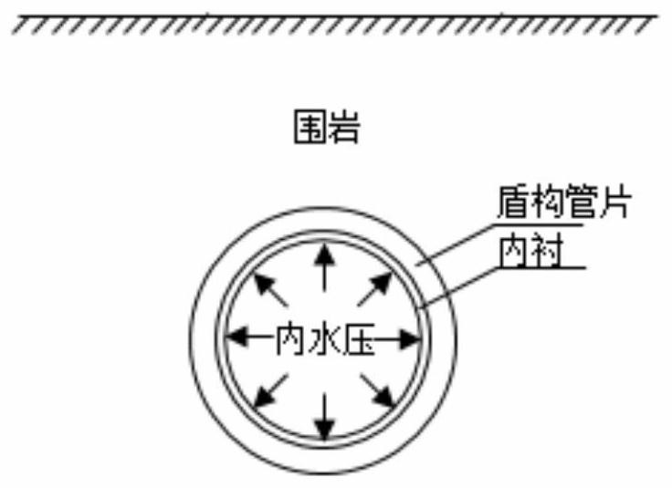
[0019] (1) Establish a calculation model of internal water pressure shared by lining, shield segments and surrounding rocks from the inside to the outside (such as figure 1 shown), the lining, shield segment and surrounding rock are decomposed into structures that independently bear the internal water pressure, and the inner diameter changes under different internal water pressures and the relationship between different internal water pressures and structures are calculated respectively. stress relationship.

[0020] In the step (1), calculate the radial displacement and stress of the lined steel pipe under different internal water pressures, the steps are:

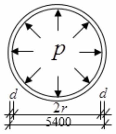
[0021] Separation of lined steel pipes, such as figure 2 As shown, let it bear the internal water pressure alone, calculate the relatio...


PUM


Abstract

The invention discloses a method for calculating a combined action of load structures under an internal water pressure of a composite lining of a shield tunnel. The method comprises the following steps of (1) building a calculation model for a lining, a shield segment and a surrounding rock which are arranged in sequence from inside to outside and bear the internal water pressure together, decomposing the lining, the shield segment and the surrounding rock into structure bodies bearing the internal water pressure separately, and calculating inner diameter changes of the structure bodies underthe action of different internal water pressures and relationships between the different internal water pressures and the stresses of the structure bodies; and (2) according to radial deformation coordination and deformation required to be controlled for seepage prevention, and in combination with a result in the step (1), determining loads sharable for the lining, the shield segment and the surrounding rock, and finally determining an actual structure of the shield tunnel under the condition of ensuring a bearable designed internal water pressure value, wherein a total internal water pressurebearable for the shield tunnel is a sum of internal water pressures bearable for the structure bodies under displacement coordination. According to the method, a mechanical concept is definite; the calculation is simple and convenient; and an effective, simple and convenient load structure method-based practical calculation method can be provided for engineering design of a complex stress structure.

Description

technical field [0001] The invention relates to the field of pressurized water conveyance tunnel engineering and basic technology, in particular to a calculation method for the combined action of load structures under water pressure in the composite lining of shield tunnels. Background technique [0002] Shield tunnels have been widely used in municipal construction such as subways. In these projects, shield segments mainly bear the water and soil pressure outside the tunnel. For the force calculation of tunnel shield segments under this condition, people have done A lot of research. However, relatively little research has been done on the calculation of the force of shield tunnels under internal water pressure, especially in the case of high internal water pressure, where the composite lining of the inner lining and the shield segment jointly bears the internal and external water and soil pressure. At present, there is still a lack of a reasonable joint action calculation ...

Claims


Application Information

Patent Timeline
Patent Type & Authority Patents(China)
IPC IPC(8): G06F30/20E21D11/08E21D11/00G06F113/14G06F119/14
CPCE21D11/00E21D11/08G06F30/20G06F2113/14G06F2119/06
Inventor 杨光华姜燕贾恺李志云徐传堡
Owner GUANGDONG RES INST OF WATER RESOURCES & HYDROPOWER
Learn More