Electrical fire monitoring device

A technology for monitoring equipment and electrical fires, which is applied to electrical equipment enclosures/cabinets/drawers, electrical components, fire alarms, etc. The effect of multiple interfaces and expanding storage capacity

Pending Publication Date: 2018-03-13
丹东华通测控有限公司
View PDF0 Cites 0 Cited by
  • Summary
  • Abstract
  • Description
  • Claims
  • Application Information

AI Technical Summary

Problems solved by technology

[0004] The purpose of the present invention is to provide an electrical fire monitoring device to solve the problem of the lack of bus interfaces, the small number of sub-station detectors that can be connected, the small storage capacity, the touch screen is always exposed outside, and dust is easy to accumulate in the existing monitoring equipment, which affects the touch screen. Sensitivity and the troublesome problem of changing the printing paper

Method used


Image

  • Electrical fire monitoring device
  • Electrical fire monitoring device
  • Electrical fire monitoring device

Examples


Embodiment Construction

[0021] The following will clearly and completely describe the technical solutions in the embodiments of the present invention with reference to the accompanying drawings in the embodiments of the present invention. Obviously, the described embodiments are only some of the embodiments of the present invention, not all of them. Based on the embodiments of the present invention, all other embodiments obtained by persons of ordinary skill in the art without making creative efforts belong to the protection scope of the present invention.

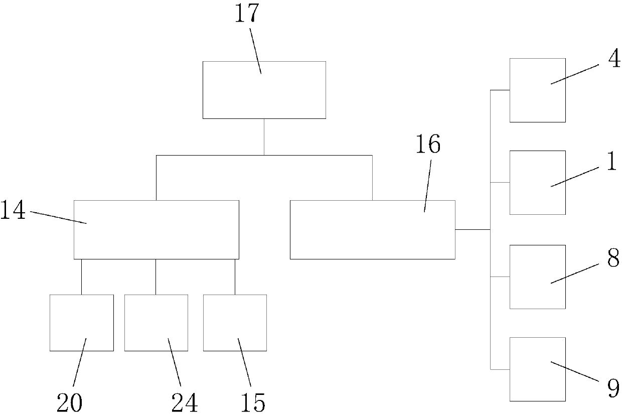
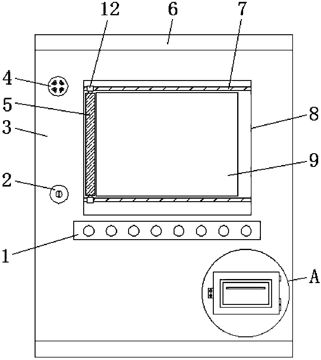
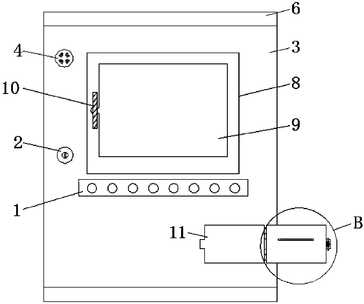
[0022] Such as Figure 1 to Figure 7 , the present invention provides an electrical fire monitoring device, comprising a cabinet body 6, one end of the cabinet body 6 is connected to a cabinet door 3 through hinge rotation, and a DC adapter 14, an industrial tablet computer 15, a power controller are installed inside the cabinet body 6 16. Air switch 17 and serial converter 24. The power controller 16 and the serial port converter 24 are located...


PUM


Abstract

The invention discloses an electrical fire monitoring device. The electrical fire monitoring device comprises a cabinet body. A direct current adapter, an industrial tablet computer, a power controller, an air switch and a serial port converter are installed inside the cabinet body. A control panel, a cabinet lock, a buzzer, a display and a printer installation groove are fixedly connected with the cabinet door. A touch screen and two crossbars are installed inside the display. The two crossbars are symmetrically located on both sides of a touchscreen respectively. The two crossbars are sleeved with rod sleeves. A movable plate is connected between the rod sleeves, and cotton cloth is fixed on the side, near the touchscreen, of the movable plate. The electrical fire monitoring device has more bus interfaces than similar devices, and number of accessible sub-station detectors is large. The movable plate, the crossbars, a pulling plate and the cotton cloth are arranged to solve a problemthat sensitivity is affected by long-term exposure of the touchscreen to external dust. A printer installation panel, the printer installation groove, and a panel lock are arranged to avoid a problemthat printing paper cannot be replaced because the cabinet door cannot be opened.

Description

technical field [0001] The invention belongs to the technical field of electrical fire monitoring systems, and in particular relates to electrical fire monitoring equipment. Background technique [0002] The electrical fire monitoring system refers to a system that can send out alarm signals, control signals and indicate the alarm position when the detected parameters in the protected line exceed the alarm setting value. The electrical fire monitoring system is characterized by the early prediction of leakage monitoring. Different from the traditional automatic fire alarm system, the early alarm of the electrical fire monitoring system is to avoid losses, while the traditional automatic fire alarm system is to reduce losses. Units with an automatic fire alarm system still need to install an electrical fire monitoring system. [0003] At present, the existing electrical fire monitoring equipment has few bus interfaces, the number of sub-station detectors that can be connecte...

Claims


Application Information

Patent Timeline
Patent Type & Authority Applications(China)
IPC IPC(8): G08B17/00H05K5/00
CPCH05K5/0017G08B17/00
Inventor 关呈功李凤丹刘伟
Owner 丹东华通测控有限公司
Why Eureka
Try Eureka