Voltage-sharing circuit for series energy storage device and voltage-sharing system comprising voltage-sharing circuit

A technology of energy storage device and voltage equalizing circuit, which is applied in control/regulation systems, output power conversion devices, electrical components, etc., can solve the problems of slow equalization speed and low modularization degree, and achieve fast equalization speed and modularization. High degree and cost reduction effect

Inactive Publication Date: 2018-03-13
HARBIN INST OF TECH
View PDF5 Cites 5 Cited by
  • Summary
  • Abstract
  • Description
  • Claims
  • Application Information

AI Technical Summary

Problems solved by technology

[0006] The present invention aims to solve the problems of low modularity and slow equalization speed in the existing equalization technology of energy storage units, and now provides a voltage equalization circuit for series energy storage devices and a voltage equalization system containing the circuit

Method used


Image

  • Voltage-sharing circuit for series energy storage device and voltage-sharing system comprising voltage-sharing circuit
  • Voltage-sharing circuit for series energy storage device and voltage-sharing system comprising voltage-sharing circuit
  • Voltage-sharing circuit for series energy storage device and voltage-sharing system comprising voltage-sharing circuit

Examples


specific Embodiment approach 1

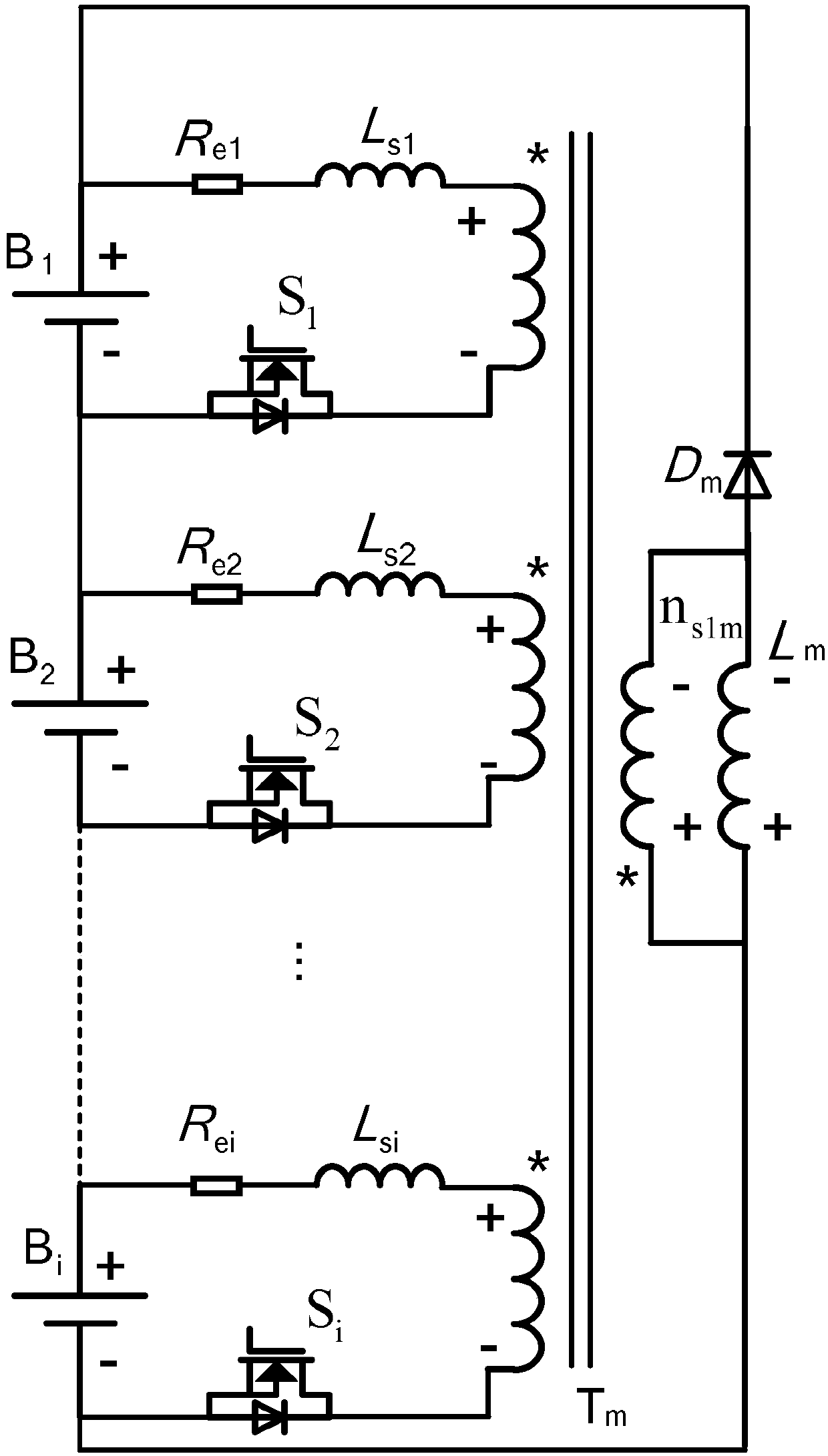
[0031] Specific implementation mode one: refer to figure 1 Specifically explain this embodiment, the voltage equalizing circuit of the series energy storage device described in this embodiment, the energy storage device is i energy storage cells connected in series, i is an integer greater than 1,

[0032] The voltage equalizing circuit includes a multi-winding transformer, and the multi-winding transformer includes i primary side windings and 1 secondary side winding. Each energy storage unit is connected in series with one primary winding through a switch circuit, and the secondary winding of the multi-winding transformer is connected in parallel with the series energy storage device.

[0033] The switching circuit includes: equivalent resistance, leakage inductance and switching tube, the switching tube is a MOSFET (Metal-Oxide-Semiconductor Field-Effect Transistor, Metal-Oxide-Semiconductor Field-Effect Transistor) switching tube; energy storage unit, equivalent resistance...

specific Embodiment approach 2

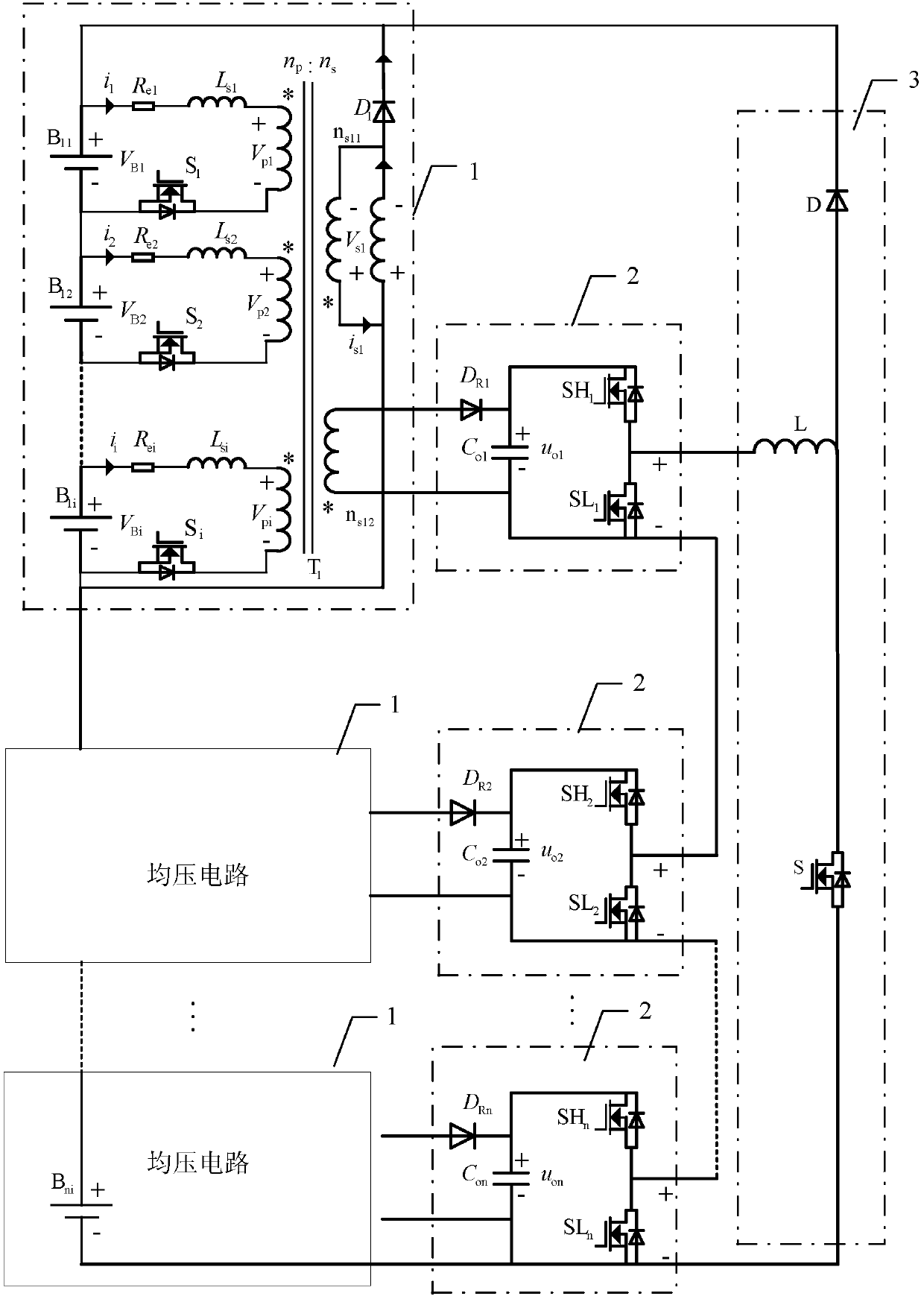
[0035] Specific implementation mode two: refer to figure 2 Describe this embodiment in detail. This embodiment is a voltage equalization system including the voltage equalization circuit described in Embodiment 1, including an intra-group equalization part and an inter-group equalization part;

[0036] The equalization part within the group includes m voltage equalizing circuits 1 , the energy storage devices in the m voltage equalizing circuits 1 are connected in series to form an energy storage system, and m is an integer greater than 1. The balance part within the group uses a multi-winding transformer to achieve voltage balance within the group.

[0037] Specifically: the secondary side of a multi-winding transformer has two windings n s1m with n s2m , where n s1m Responsible for feeding back the excitation energy of the transformer to the energy storage device itself; n s2m It is responsible for taking out the excitation energy of the transformer and feeding it back ...

specific Embodiment

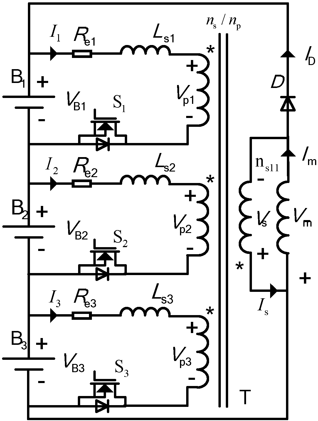
[0043] Specific embodiment: assuming i=3, the energy storage device includes 3 energy storage cells, which are respectively denoted as B 1 , B 2 and B 3 , corresponding to a voltage of V B1 , V B2 and V B3 , and satisfy V B1 >V B3>(V B1 +V B2 +V B3 ) / 3>V B2 . Then there are:

[0044] Part I: Intragroup Balance

[0045] The voltage of the energy storage device is lower than the average voltage, and the excitation energy is fed back to the energy storage device itself. Such as image 3 As shown, energy storage unit B 1 , B 2 and B 3 respectively through the switch S 1 , S 2 and S 3 connected to three separate transformer windings with the same turns ratio, and the switch S 1 , S 2 and S 3 driven by the same PWM signal. R ei (i=1, 2, 3) is the equivalent resistance, L si (i=1, 2, 3) is the leakage inductance. Figure 4 Waveforms of driving and main operating parameters are shown.

[0046] When switch S 1 , S 2 and S 3 When turned on, the transformer ...


PUM


Abstract

The invention discloses a voltage-sharing circuit for a series energy storage device and a voltage-sharing system comprising the voltage-sharing circuit, and relates to the technical field of large-scale series energy storage cell voltage balancing. The invention aims at solving problems that the conventional energy storage cell balancing technology is low in modularization degree and is slow in balancing speed. In the voltage-sharing circuit, two ends of each energy storage cell are in parallel connection with one primary side winding, and a secondary side winding of a multi-winding transformer and an energy storage device are connected in series to form a closed loop, wherein the numbers of turns of i primary side windings are equal. Switching circuits are used for the charging and discharging of the energy storage cells between the energy storage cells and the primary side windings, and the drive signals of all switching circuits are the same. m cascaded half-bridge converts and oneBoost converter are employed to achieve the voltage balance between m voltage-sharing circuits.

Description

technical field [0001] The invention belongs to the technical field of voltage equalization of large-scale series-connected energy storage cells. Background technique [0002] With the continuous advancement of new energy technology, the wide application of new energy vehicles and distributed energy, energy storage devices have been rapidly developed and applied. One of the key technologies that restricts the wide application of energy storage devices is the rapid equalization technology between series energy storage cells. Energy storage monomers, such as supercapacitors, lithium batteries, lead-acid batteries, etc., have low monomer voltage and require a large number of monomers to be used in series. Due to the inconsistency of the monomer parameters, the voltage of the series monomers will be unbalanced during use. The service life of the cells with too high voltage decays quickly, which affects the service life of the entire energy storage device; the cells with too lo...

Claims


Application Information

Patent Timeline
Patent Type & Authority Applications(China)
IPC IPC(8): H02M3/156H02M3/335
CPCH02M3/156H02M3/33523H02M1/007
Inventor 凡绍桂安群涛张东邹存芝段建东孙力
Owner HARBIN INST OF TECH
Why Eureka
Try Eureka