a medical guide wire

A guide wire and helical groove technology, applied in the field of medical equipment, can solve the problems such as the inability to adjust the flexibility, hardness and bending degree of the guide wire, and the inability to adjust and use it, so as to achieve good controllability and pushing force, convenient guide wire, Easy-to-control effects

Active Publication Date: 2020-07-03
董鹏
View PDF5 Cites 0 Cited by
  • Summary
  • Abstract
  • Description
  • Claims
  • Application Information

AI Technical Summary

Problems solved by technology

However, in the use of this patent, the softness, hardness and bending degree of the guide wire cannot be fully adjusted, and it cannot be adjusted and used according to the doctor's surgical needs.

Method used


Image

  • a medical guide wire
  • a medical guide wire
  • a medical guide wire

Examples


Embodiment 1

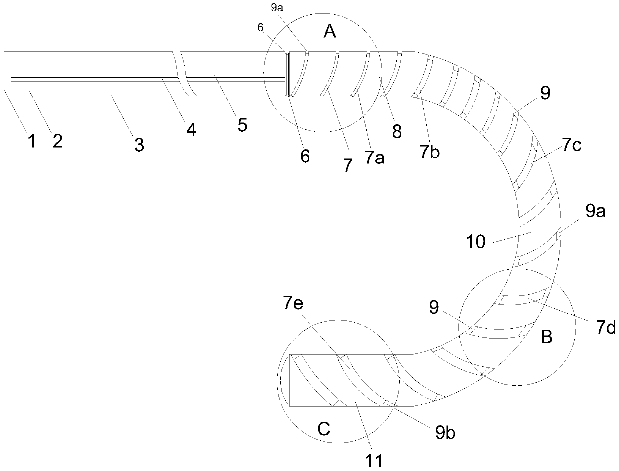
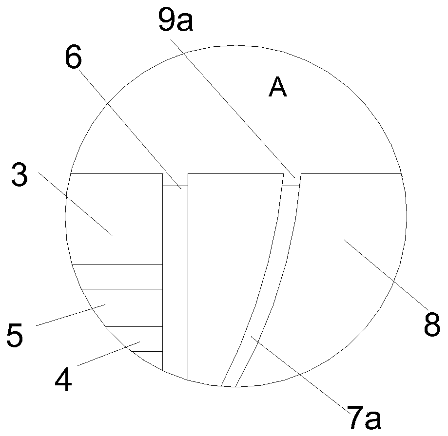
[0031] Such as Figure 1 to Figure 4 As shown, the present invention provides a medical guide wire, the outer diameter of the guide wire is in the range of 0.60mm-0.80mm, the preferred outer diameter is 0.6mm, 0.65mm or 0.80mm, and the medical guide wire includes a metal inner core 3 and the resin layer arranged on its outer layer, and one end of the inner core 3 is provided with a connection part 1 for rigid connection with other guide wires of different materials and hardness. The guide wire is preferably made of stainless steel or nickel-titanium alloy, and superelastic alloys such as Ni-Ti alloy are the best options. The bending radius R of the curved flexible front end of the medical guide wire can range from 0.2 mm to 20 mm, and preferably range from 10 mm to 15 mm. Generally, the length of the front end of the curved portion may be 5mm-40mm, preferably 10mm-30mm. The length range of the guide wire is preferably between 100cm-450cm, and more preferably between 300cm-40...

Embodiment 2

[0033] This embodiment is further improved on the basis of Embodiment 1, the difference is:

[0034] Such as Figure 5 , 6 As shown, the medical guide wire provided by the present invention implements another preferred technical solution, specifically, the bottom of the first positioning groove 9a is provided with a third positioning groove 9c whose width is smaller than that of the first positioning groove 9a, and the third positioning groove 9a The positioning grooves 9c are arranged at the front ends of the head portion 8 and the arc portion 10, and the two third positioning grooves 9c are arranged opposite to each other.

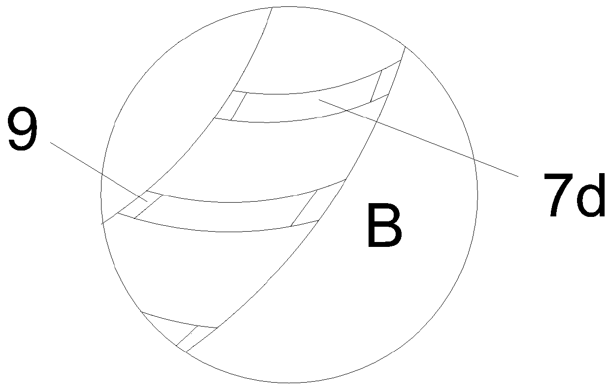
[0035] Such as Figure 7 As shown, the fourth positioning groove 9d and / or the fifth positioning groove 9e with a rectangular cross section are provided at the middle end of the arc portion 10, and the fourth positioning groove 9d and / or the fifth positioning groove 9e are oppositely arranged and Misplacement setting, the fourth positioning groove 9d ...

Embodiment 3

[0038]The present invention also provides a spring used in conjunction with a medical guide wire, and the structure of the spring is set corresponding to the structure of the medical guide wire provided in embodiment 1 or embodiment 2.


PUM

PropertyMeasurementUnit
radiusaaaaaaaaaa
sizeaaaaaaaaaa
lengthaaaaaaaaaa

Abstract

The invention relates to the technical field of medical instruments, in particular to a medical guide wire. The medical guide wire comprises a metal inner core and a resin layer arranged on the outerlayer of the metal inner core. One end of the inner core is provided with a connecting part which is used for being in rigid connection with other guide wires of different materials and hardness. Theguide wire has a linear part and a bent part with the bent front end. The linear part is provided with a first groove. The bent part comprises a head part, an arc-shaped part and a tail part which aresequentially connected from end to end. The bent part is provided with a spiral groove group. The first groove and the spiral groove group can be internally provided with springs matched in inner diameter or adaptive in elasticity, hardness and tenacity. The hardness and elasticity of the springs can be replaced or selected according to the type of surgery. The guide wire can be used in cooperation with the spring of a proper size and structure, or the tenacity, hardness and strength of the guide wire is adjusted by replacing the springs of different elasticity so as to more conveniently control the guide wire.

Description

technical field [0001] The invention belongs to the technical field of medical equipment, in particular to a medical guide wire. Background technique [0002] Guidewires are medical devices used to guide catheters, stents, etc. to target sites in blood vessels and other cavities. During the operation, when the guide wire passes through a particularly tortuous blood vessel, the angle needs to be adjusted at any time in order to pass through the blood vessel smoothly. During the operation, the guide wire needs to have a soft head end, and at the same time, the proximal end has good maneuverability and pushing force, and at the same time, the guide wire is required to have an appropriate size and structure. However, due to the complexity of the lesion and the curved nature of the blood vessel itself, it is difficult for the traditional straight or curved guidewire to take into account the above-mentioned performances at the same time, and it will be limited when entering the b...

Claims


Application Information

Patent Timeline
Patent Type & Authority Patents(China)
IPC IPC(8): A61M25/09A61M25/00
CPCA61M25/0043A61M25/0045A61M25/0068A61M25/09A61M2025/0046A61M2025/09133A61M2025/0915A61M2025/09083
Inventor 董鹏
Owner 董鹏
Why Eureka
Try Eureka