
Machining method for thin-wall shaft sleeve with two ends supported and middle suspended

A processing method and technology for thin-walled shafts, which are applied in the field of aero-engine assembly and processing, can solve the problems of the precise outer diameter of the bushing, the scrapped cylindricity, and the deformation of the bushing, so as to solve the problems of scrapped processing, high processing efficiency and high cost performance. Effect

Active Publication Date: 2018-03-16
AECC AVIATION POWER CO LTD
View PDF6 Cites 0 Cited by
  • Summary
  • Abstract
  • Description
  • Claims
  • Application Information

AI Technical Summary

Problems solved by technology

The characteristics of the assembly structure of the bushing lead to the high-speed rotation of the grinding head during the grinding process of the bushing. When the bushing touches the suspended part, the bushing and the grinding head are squeezed, and the bushing is deformed by the cutting force, resulting in the precise outer diameter of the bushing. Size and cylindricity "let the knife" be scrapped

Method used


Image

  • Machining method for thin-wall shaft sleeve with two ends supported and middle suspended
  • Machining method for thin-wall shaft sleeve with two ends supported and middle suspended

Examples


Embodiment

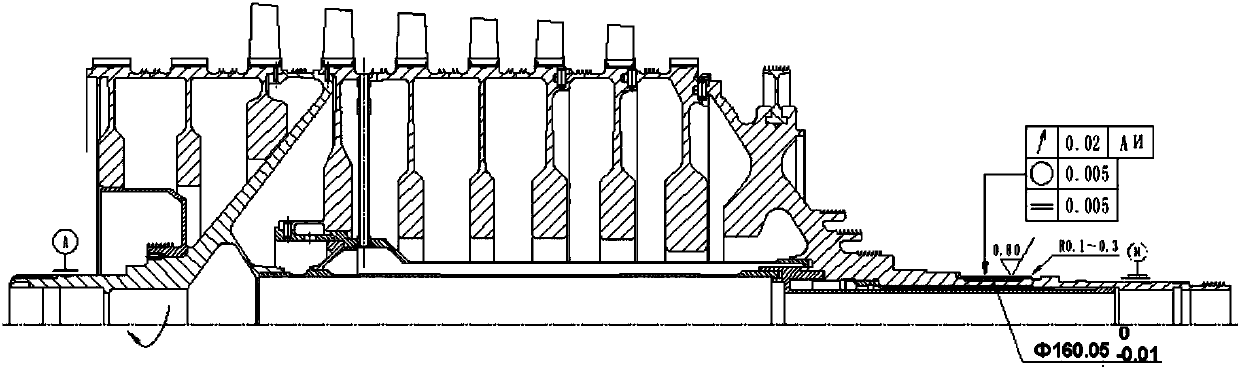
[0034] 1) Installation and alignment: Install the rotor on the horizontal lathe, and the front and rear journals of the alignment rotor run out no more than 0.01mm.

[0035] 2) Rough turning: For the material of the parts of the thin-walled bush, select the corresponding machine-added blade material and R, rough turn the outer circle of the bush, and leave a margin of 0.10-0.15mm on one side.

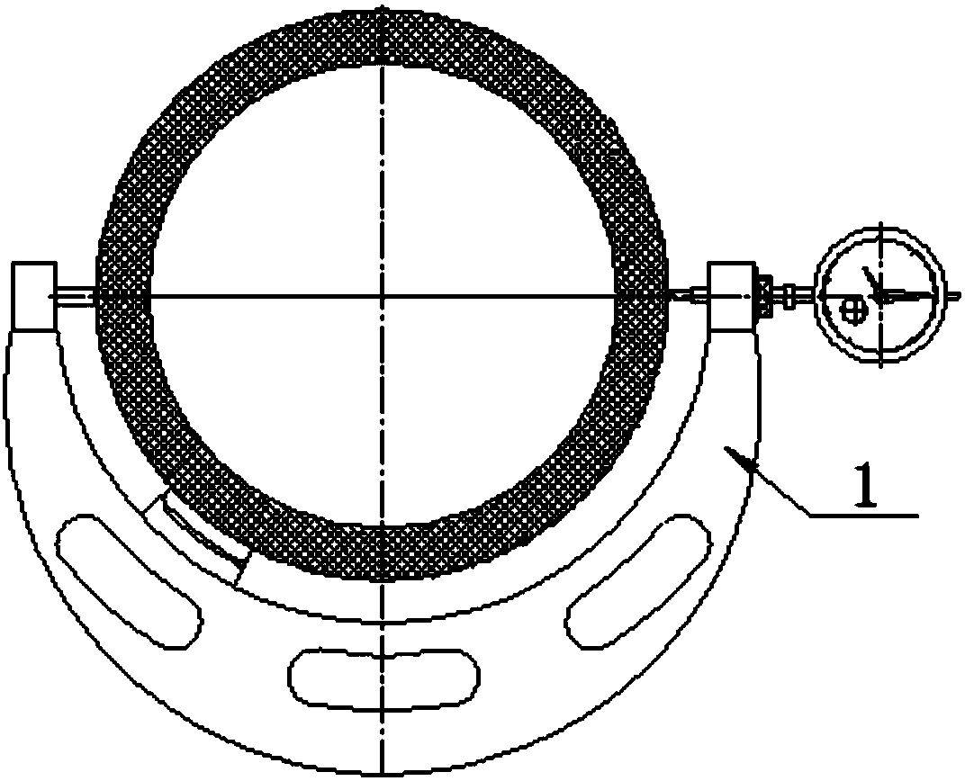
[0036] 3) Finish turning: The runout of the front and rear journals of the rotor is not greater than 0.01, the outer circle of the bushing is finished, the blade number is VBGT160401-F1CP500, and the feed rate is within 0.018-0.032. After each cut, it is on the outer circle of the bushing Draw the grid with a marker pen, measure 6 sections in detail, and measure the outer diameter value of 8 points for each section, leaving a margin of 0.015mm on one side of the smallest diameter.

[0037] 4) Chamfering: 0.2-0.4mm chamfering on the sharp edge of the shaft sleeve.

[0038] 5) Inspection...


PUM

PropertyMeasurementUnit
Widthaaaaaaaaaa

Abstract

The invention discloses a machining method for a thin-wall shaft sleeve with the two ends supported and the middle suspended. The machining method comprises the following steps of step 1, alignment, wherein both the runout of the front journal and the runout of the rear journal of an alignment rotor are smaller than 0.01 millimeter; step 2, rough turning, wherein rough turning is carried out on the excircle of a bush, and the single edge margin ranges from 0.10 millimeter to 0.15 millimeter; step 3, finish turning, wherein both the runout of the front journal and the runout of the rear journalof an alignment rotor are smaller than 0.01 millimeter, finish turning is carried out on the excircle of the bush, and the single edge margin of the part with the minimum diameter is 0.015 millimeter; step 4, chamfering, wherein chamfering is carried out on the sharp edge of the bush for 0.2 millimeter to 0.4 millimeter; step 5, checking, wherein both the runout of the front journal and the runout of the rear journal of an alignment rotor are smaller than 0.01 millimeter; step 6, finish grinding, wherein grinding is carried out on the excircle of the bush to the upper deviation; and step 7, precision polishing, wherein the bush is polished with abrasive paper for metallograph to guarantee the dimensions and the roughness of Ra 0.8, and then machining is completed. By adopting the machining method for a thin-wall shaft sleeve, with the two ends supported and the middle suspended, made of difficult-to-machine materials, the problems that a bush is scraped during machining, and measurement errors are large are successfully solved, the percent of pass of machined bushes reaches 100%, the efficiency is improved by 50%, and in a word, the machining method for a thin-wall shaft sleeve with the two ends supported and the middle suspended is high in efficiency and cost performance.

Description

technical field [0001] The invention belongs to the technical field of assembly and processing of aero-engines, and in particular relates to a processing method for a thin-walled shaft sleeve with supports at both ends suspended in the middle. Background technique [0002] Aviation rotor components have high technical requirements, high processing difficulty, and strict requirements on process technology; the product structure is complex, in which the back bearing bush is assembled on the rear journal with a margin for combined processing, and the bush is a thin-walled part with a wall thickness of only 2mm. The material is difficult-to-machine material GH698. After being assembled on the rear axle journal, the bushing is supported at both ends and suspended in the middle. The length of both ends is 9mm, and the length of the middle is 60mm. The diameter is Ф160mm, and the tolerance is 0.01mm. The characteristics of the assembly structure of the bushing lead to the high-spe...

Claims


Application Information

Patent Timeline
IPC IPC(8): B23P15/00
CPCB23P15/00
Inventor 何朝霞陈金平樊铁艳杨桢任江华曹朋金静王建
Owner AECC AVIATION POWER CO LTD
Features
  • Generate Ideas
  • Intellectual Property
  • Life Sciences
  • Materials
  • Tech Scout
  • Unparalleled Data Quality
  • Higher Quality Content
  • 60% Fewer Hallucinations
Learn More