
Gas cylinder transportation cart system for power grid and control method

A technology for transporting trolleys and gas cylinders, which is applied in the field of electric power transportation, can solve the problems of consuming a lot of energy and operating skills, technical difficulty, and high labor intensity, and achieve the effect of simple structure, simplified control procedures, and clear organization

Inactive Publication Date: 2018-03-16
HAIBEI POWER SUPPLY COMPANY STATE GRID QINGHAI ELECTRIC POWER +1
View PDF0 Cites 5 Cited by
  • Summary
  • Abstract
  • Description
  • Claims
  • Application Information

AI Technical Summary

Problems solved by technology

[0002] With the continuous development of the power system, the workload of technical transformation and replacement of CT and other equipment in the substation is increasing, and the gas leakage points caused by the quality problems, environmental problems and long-term running time of the combined electrical equipment are increasing year by year. This makes the work of quick gas replenishment difficult and labor-intensive
[0003] Existing gas cylinders are mainly transported by manpower. Usually the gas cylinders fall on the ground, and workers need to stand them up and then carry them onto the vehicle, or simply roll them manually. Not to mention that rolling the gas cylinders requires a lot of energy and operating skills However, it takes at least two people to work together to stand up the gas cylinder that has fallen to the ground. Therefore, it is quite labor-intensive to set up the gas cylinder manually and transport the gas cylinder manually, and it may cause accidents and dangers due to improper operation of the workers.

Method used


Image

  • Gas cylinder transportation cart system for power grid and control method
  • Gas cylinder transportation cart system for power grid and control method
  • Gas cylinder transportation cart system for power grid and control method

Examples


Embodiment Construction

[0026] The present invention will be described in detail below in conjunction with specific embodiments.

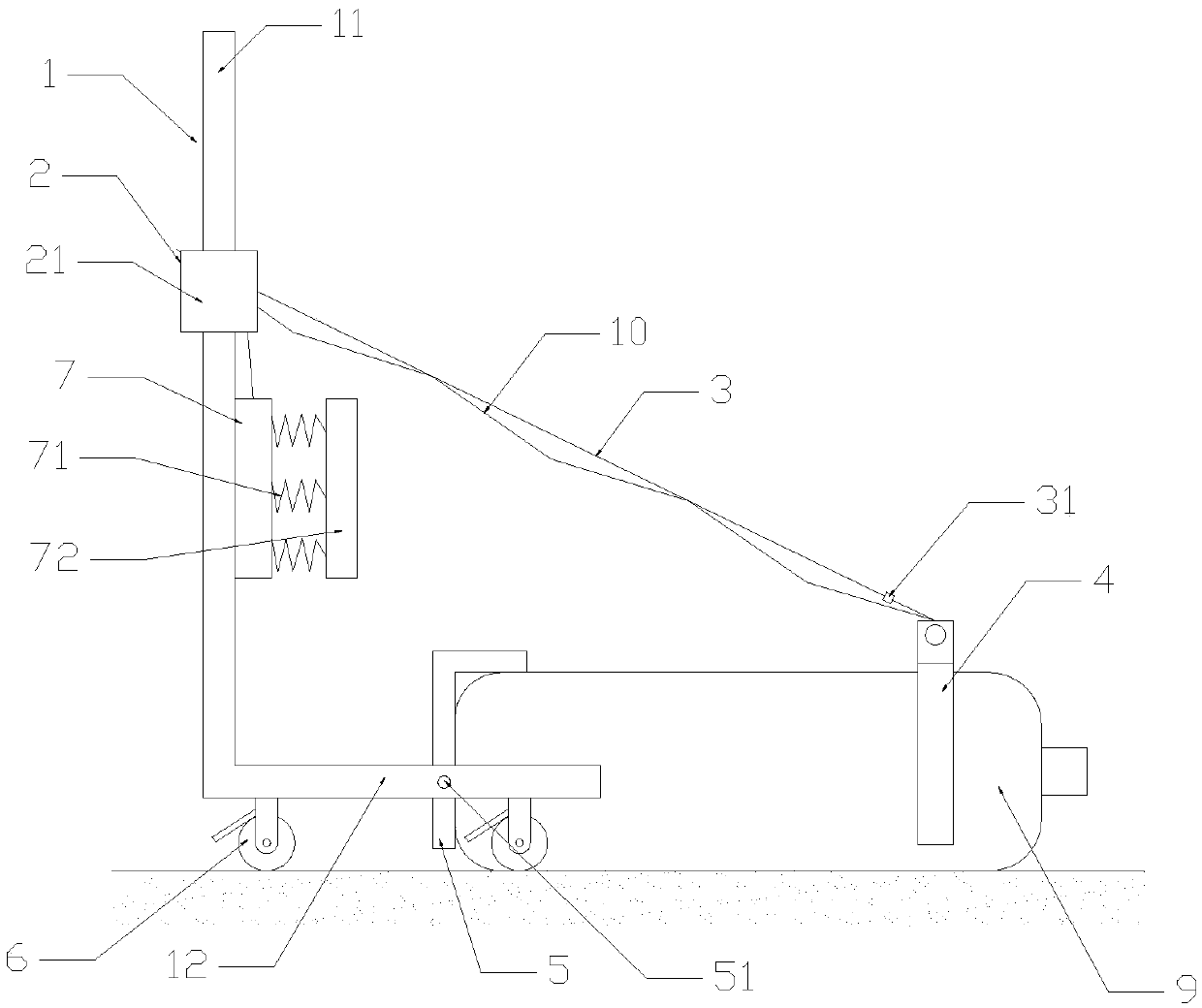
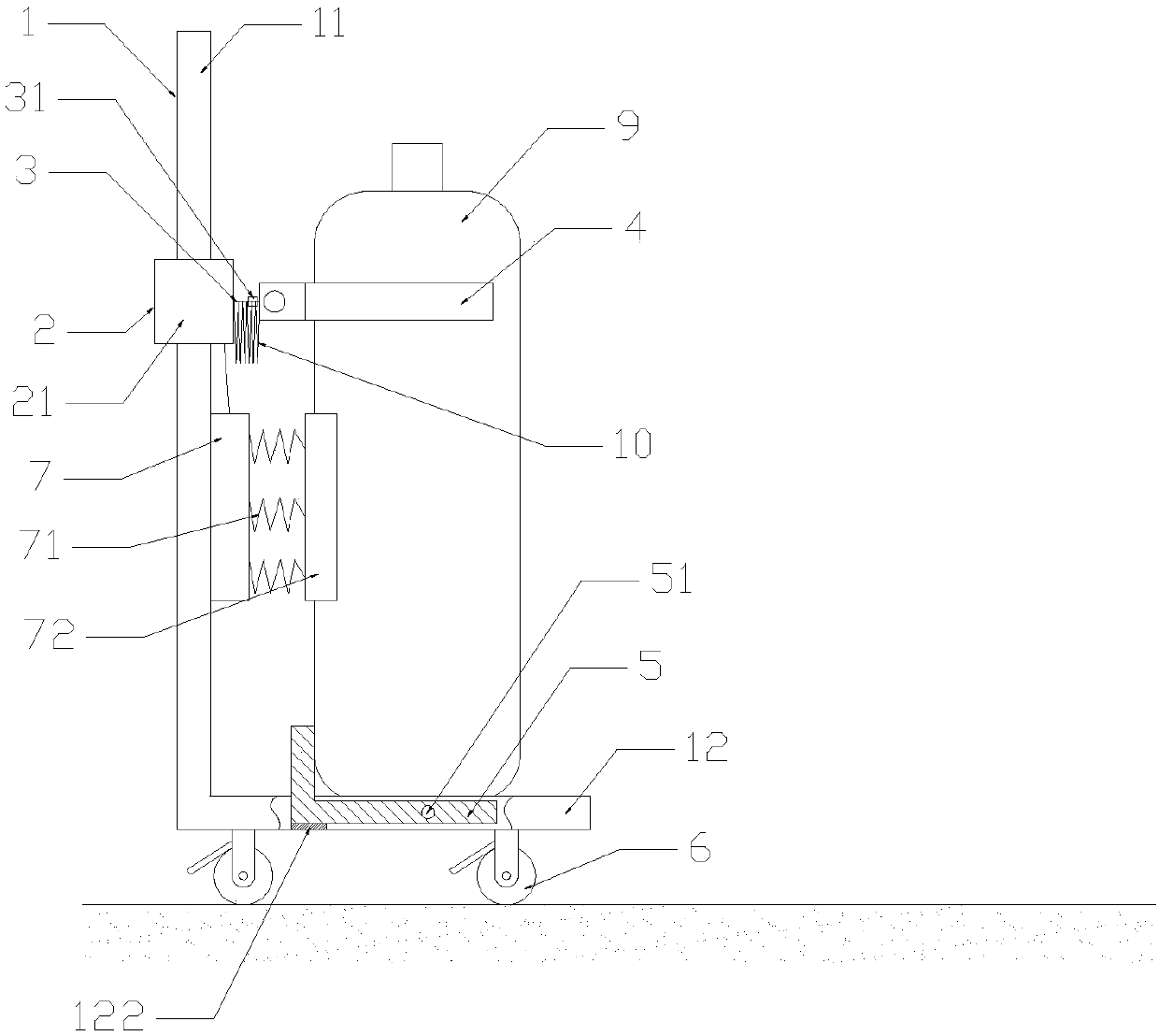
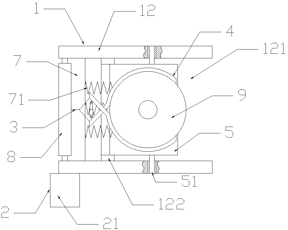
[0027] Such as Figure 1-5 As shown, this embodiment includes an L-shaped frame body 1 , a rotary drive device 2 , a pull wire 3 , a holding clip 4 and a rotating plate 5 .

[0028] The frame body 1 includes a bottom 12 and a vertical portion 11 erected vertically on the bottom 12 , and the rotation driving device 2 is arranged on the vertical portion 11 of the frame body 1 .

[0029] Such as Figure 4 As shown, the rotary drive device 2 includes a drive motor 21 and a bobbin 22; the two ends of the bobbin 22 are connected to both sides of the vertical portion 11 of the frame body 1 through bearings, and the height of the bobbin 22 is preferably kept The position between the elbow and the shoulder of the person is more ergonomic, and the bobbin 22 can be used as a push rod when not in use, so that the worker can push the dolly. The middle part of the bobbin 22 is fixed...


PUM


Abstract

The invention belongs to the field of electric power transportation, and in particular relates to a gas cylinder transport trolley system and control method for power grids that can safely and automatically erect gas cylinders that fall to the ground and can automatically transport the gas cylinders onto the vehicle; the invention includes an L-shaped frame , a rotary drive device, a backguy, a clip and a turntable; the rotary drive device is arranged on the vertical part of the frame body, and the output part of the rotary drive device is connected to one end of the backguy; the other end of the backguy is connected to the clip; the The bottom of the frame is provided with an opening, and the rotating plate is located at the opening, and the rotating plate is connected to the bottom of the frame through the rotating shafts on both sides; the bottom surface of the bottom of the frame is provided with casters; Devices, baffles, turntables, and pull wires are all equipped with corresponding sensors or inductive switches. The use of each sensor or inductive switch in conjunction with each other realizes the automation of the system and also ensures the safety of the system; the system provides A control method is also provided on the basis of the structure.

Description

technical field [0001] The invention belongs to the field of electric power transportation, and in particular relates to a gas cylinder transportation trolley system and a control method for a power grid. Background technique [0002] With the continuous development of the power system, the workload of technical transformation and replacement of CT and other equipment in the substation is increasing, and the gas leakage points caused by the quality problems, environmental problems and long-term running time of the combined electrical equipment are increasing year by year. This makes the work technically difficult and labor-intensive. [0003] Existing gas cylinders are mainly transported by manpower. Usually the gas cylinders fall on the ground, and workers need to stand them up and then carry them onto the vehicle, or simply roll them manually. Not to mention that rolling the gas cylinders requires a lot of energy and operating skills However, it takes at least two people ...

Claims


Application Information

Patent Timeline
IPC IPC(8): B62B3/04B62B3/10
CPCB62B3/04B62B3/104B62B2202/022B62B2203/44B62B2203/70
Inventor 庞伟生范玉亮王一博丁润玲郑麟刘小凡牛成海樊晓苹梁斌陆峙酉陈凯朱朝平
Owner HAIBEI POWER SUPPLY COMPANY STATE GRID QINGHAI ELECTRIC POWER
Learn More