Upper buttress structure for shock insulation reinforcement of existing building and construction method of upper buttress structure

A technology for existing buildings and seismic isolation, applied in building construction, construction, building maintenance, etc., can solve the problems of high structural safety risk, large column damage, long support time, etc., and achieve good social and technical economic benefits. , Clear structural stress model, reliable effect of anchoring measures

Active Publication Date: 2018-03-16
南京分震建筑科技有限公司
View PDF8 Cites 0 Cited by
  • Summary
  • Abstract
  • Description
  • Claims
  • Application Information

AI Technical Summary

Problems solved by technology

[0009] The above two methods have great difficulties in construction. The first method is to cut off the column manually. In order to reserve the anchor steel bar of the column, it is necessary to use a small hammer to slowly chisel out the concrete. The construction speed is slow and the damage to the column bigger
The second method involves a large amount of welding work on site, and no direct anchoring measures are taken for the main reinforcement of the column
The consumption of steel is large, the production is labor-intensive, the jacking time is long, the safety risk to the structure is large, and the project cost is high

Method used


Image

  • Upper buttress structure for shock insulation reinforcement of existing building and construction method of upper buttress structure
  • Upper buttress structure for shock insulation reinforcement of existing building and construction method of upper buttress structure
  • Upper buttress structure for shock insulation reinforcement of existing building and construction method of upper buttress structure

Examples


Embodiment Construction

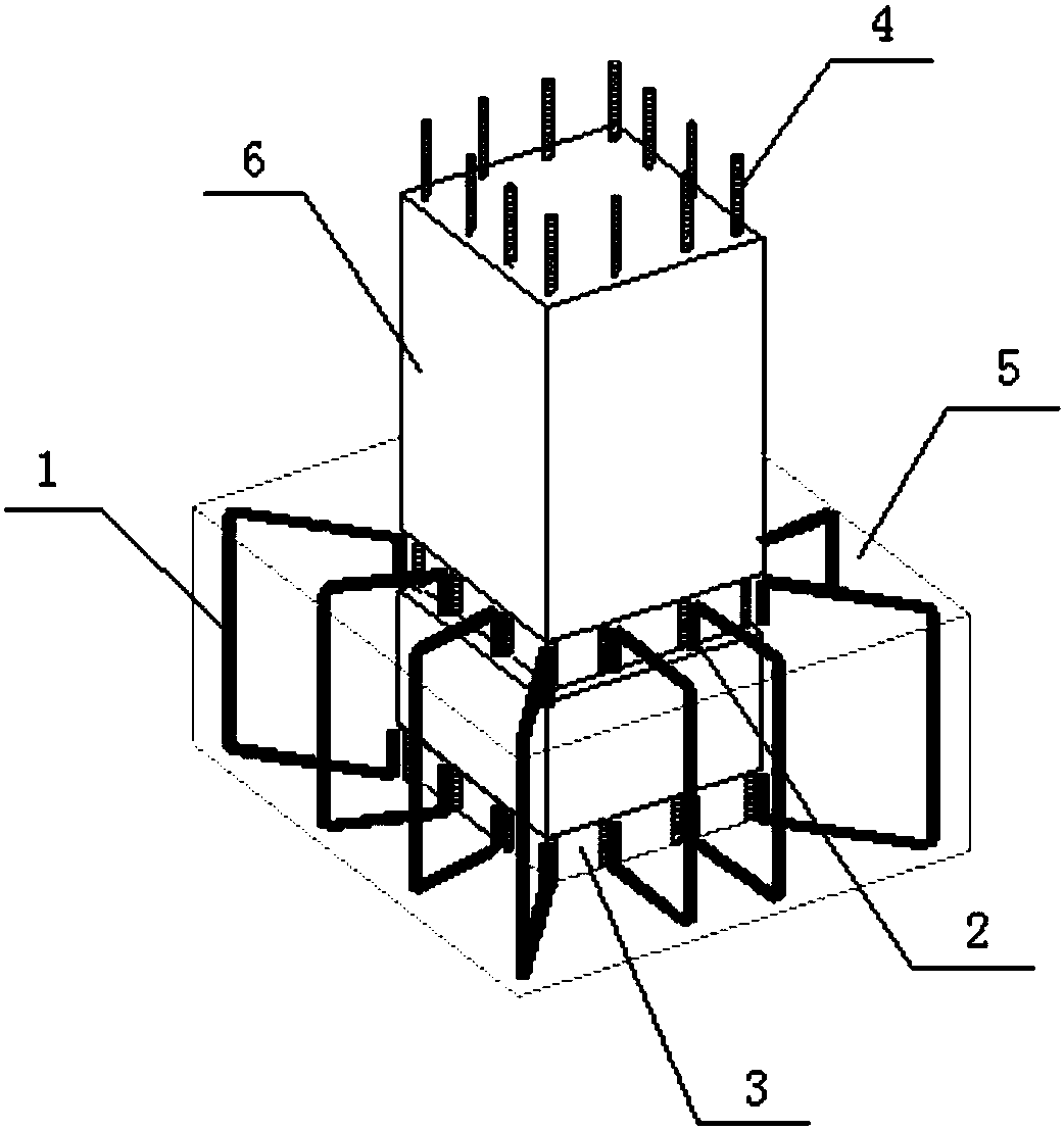
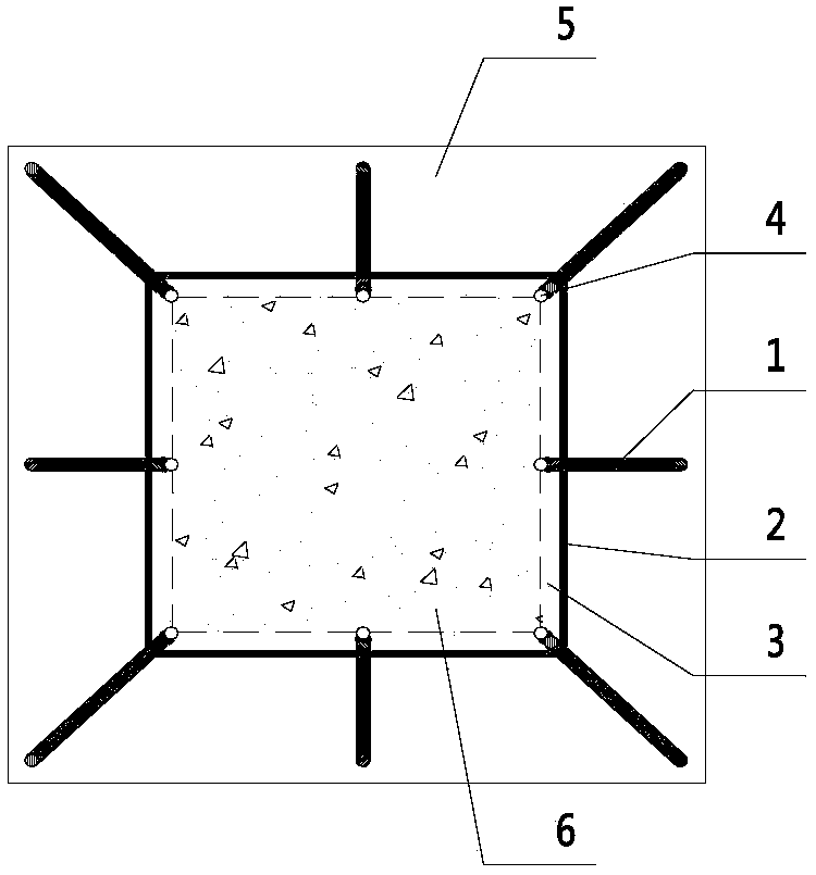
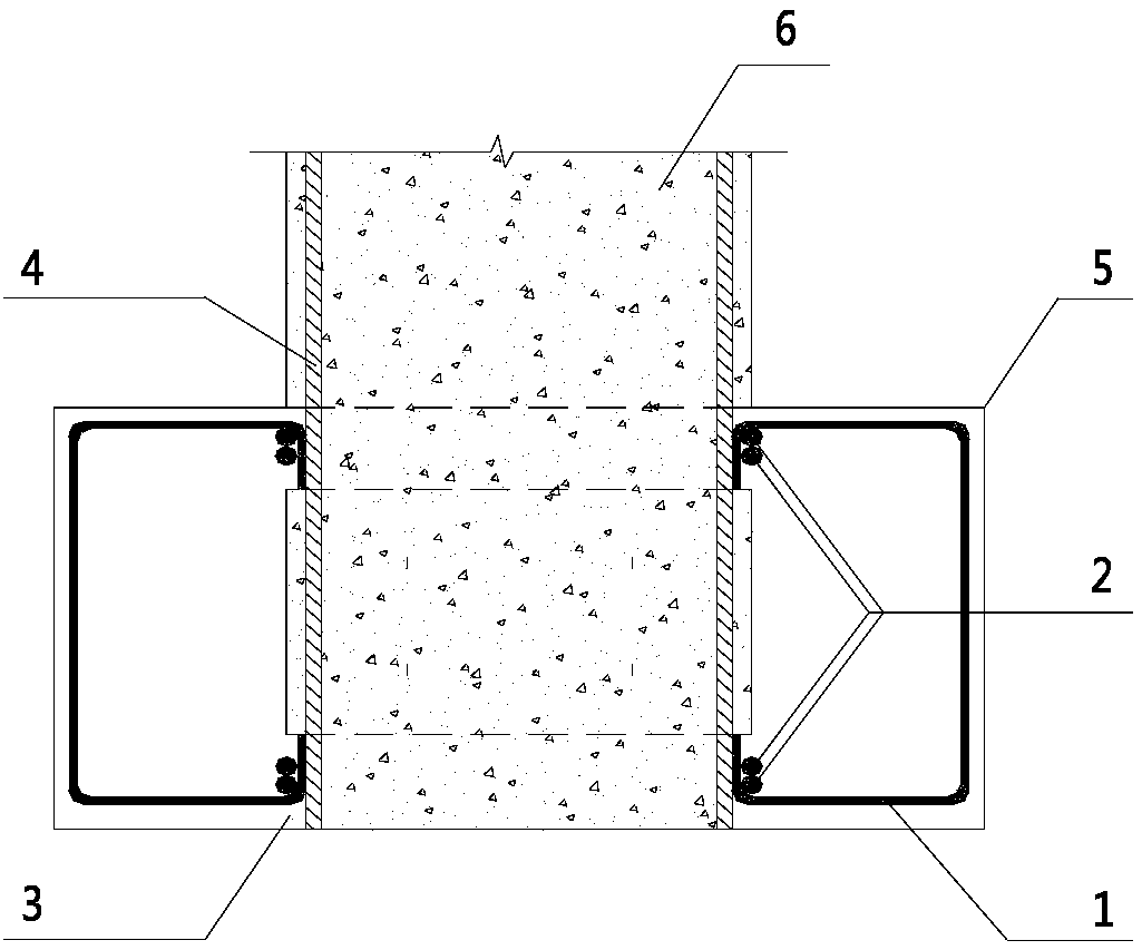
[0056] The following will clearly and completely describe the technical solutions in the embodiments of the present invention with reference to the accompanying drawings in the embodiments of the present invention. Obviously, the described embodiments are only some, not all, embodiments of the present invention. The following description of at least one exemplary embodiment is merely illustrative in nature and in no way taken as limiting the invention, its application or uses. Based on the embodiments of the present invention, all other embodiments obtained by persons of ordinary skill in the art without creative efforts fall within the protection scope of the present invention. The relative arrangements, expressions and numerical values ​​of components and steps set forth in these embodiments do not limit the scope of the present invention unless specifically stated otherwise. At the same time, it should be understood that, for the convenience of description, the sizes of the...


PUM


Abstract

The invention discloses an upper buttress structure for shock insulation reinforcement of an existing building and a construction method of the upper buttress structure. The upper buttress structure comprises bearing frame columns of original structures, newly-poured column-embraced steel bar concrete parts and connecting structures between the bearing frame columns and the newly-poured column-embraced steel bar concrete parts. The connecting structures comprise a plurality of anchorage bars, horizontal closed hoopings and new-old concrete combining parts. All the anchorage bars and column main bars of original bearing frame columns can be welded and fixed to form lantern-type bars. The horizontal closed hoopings can tightly hoop the welding positions of all the anchorage bars and the column main bars. The new-old concrete combining parts are formed by means of the method that outer wrapped concrete layers of the bearing frame columns of the original structures are chiseled to expose the welding position points of the column main bars. The column-embraced steel bar concrete parts are poured and formed on the peripheries of the bearing frame columns of the original structures. Therefore, the upper buttress structure is a new-old concrete combined structure, the original structure columns are sufficiently utilized, the bearing frame column main bar anchoring measures are cleared,the structure is concise, and construction is rapid.

Description

technical field [0001] The invention belongs to the technical field of seismic isolation reinforcement and transformation of building structures, and in particular relates to an upper pier structure for seismic isolation reinforcement of existing buildings, which is suitable for transformation projects such as translation of existing buildings, adding a basement, and the like. It is especially suitable for the seismic reinforcement project of existing buildings in the earthquake zone using seismic isolation technology. [0002] The invention also relates to a construction method of an upper pier for seismic isolation and reinforcement of an existing building. Background technique [0003] For existing buildings to be retrofitted with seismic isolation, it is usually necessary to install a seismic isolation layer at the bottom of the building. The specific method in the prior art is: first cut off the load-bearing frame column above the top of the foundation to the height of...

Claims


Application Information

Patent Timeline
Patent Type & Authority Applications(China)
IPC IPC(8): E04G23/06E04H9/02
CPCE04G23/06E04H9/027
Inventor 鲁风勇李小敏
Owner 南京分震建筑科技有限公司
Why Eureka
Try Eureka