
Compact jet flow air extractor for ship

A jet pumping, compact technology, applied in the direction of jet pumps, machines/engines, non-volume pumps, etc., can solve the problems of difficult to place ships, limited space of ships, large gas friction, etc., to ensure functional integrity and convenience Operation and maintenance, effect of volume reduction

Inactive Publication Date: 2018-03-16
NO 719 RES INST CHINA SHIPBUILDING IND
View PDF5 Cites 6 Cited by
  • Summary
  • Abstract
  • Description
  • Claims
  • Application Information

AI Technical Summary

Problems solved by technology

[0004] (1) The space on the ship is limited, and the space occupied by each part of the existing jet air extractor is relatively large, so that the volume of the jet air extractor is relatively large, and it is difficult to place it on the ship
[0005] (2) There are restrictions on noise when working on a ship, and most of the existing jet air extractors do not consider the optimization of the acoustic flow field. The friction of the gas in the internal structure and pipeline of the air extractor is relatively large, and the vibration produces large noise. noise
[0006] At the same time, the distance between the nozzle and the diffuser of the existing jet air extractor cannot be adjusted, which is not flexible enough

Method used


Image

  • Compact jet flow air extractor for ship
  • Compact jet flow air extractor for ship

Examples


Embodiment Construction

[0027] The present invention will be described in further detail below in conjunction with the accompanying drawings and embodiments.

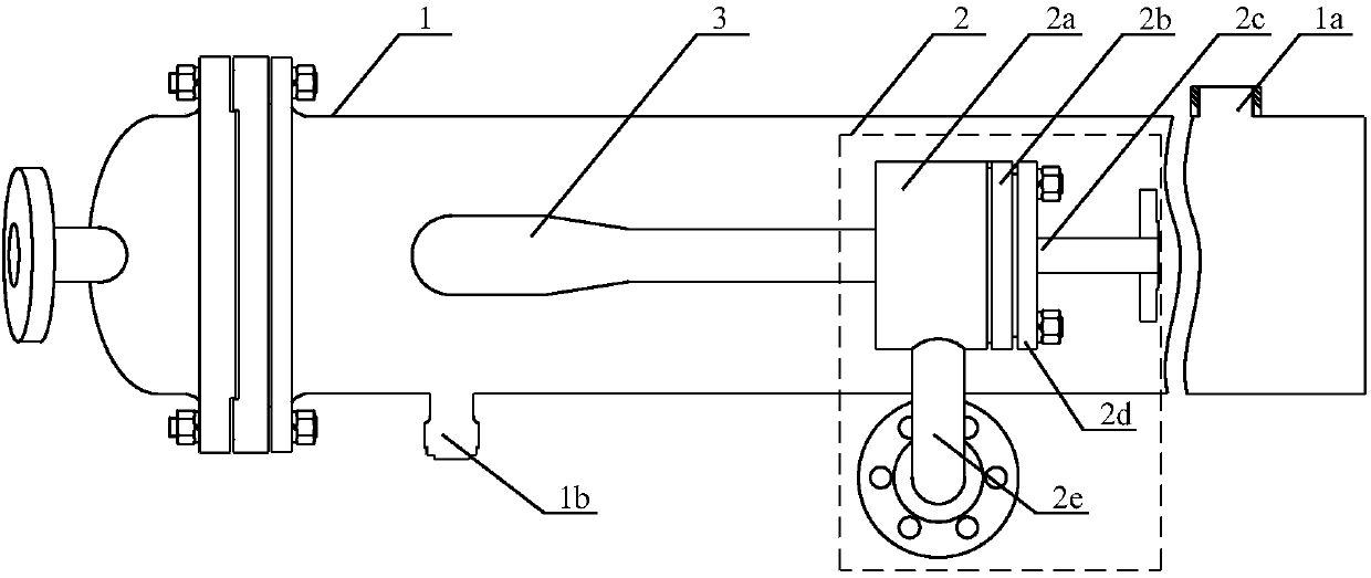
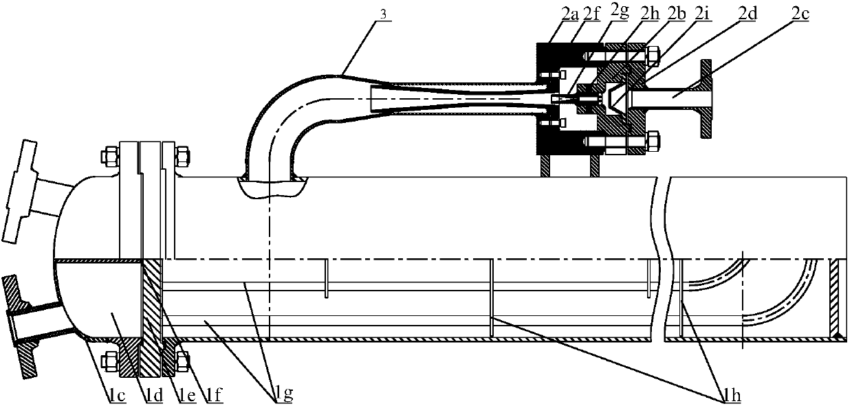
[0028] see figure 1 As shown, the compact jet air extractor for ships in the embodiment of the present invention includes a condenser 1, and a jet air extraction assembly 2 is arranged on the condenser 1, and the output end of the jet air extraction assembly 2 passes through an arc The connecting pipe 3 communicates with the input end of the condenser 1.

[0029] see figure 1 and figure 2 As shown, the jet air extraction assembly 2 includes a steam drainage tube base 2d, a nozzle base 2b, a receiving chamber 2a and a diffuser 2f that communicate with each other and are connected in sequence. The receiving chamber 2a is a hollow structure, and the steam drainage tube base 2d is provided with The arc-shaped steam draft pipe 2c is provided with a nozzle 2g on the nozzle seat 2b, and the distance between the nozzle 2g and the nozzle seat 2b ca...


PUM


Abstract

The invention discloses a compact jet flow air extractor for a ship, and relates to the technical field of gas ejectors. The compact jet flow air extractor for a ship comprises a condenser and a jet flow gas extraction unit. The jet flow gas extraction unit comprises a steam drainage pipe base, a nozzle base, a receiving chamber and a diffuser, wherein the steam drainage pipe base, the nozzle base, the receiving chamber and the diffuser communicate with one another and are connected in sequence. An arc-shaped steam drainage pipe is arranged on the steam drainage pipe base. A nozzle is arrangedon the nozzle base. The output end of the steam drainage pipe communicates with the input end of the nozzle. The output end of the nozzle penetrates through the receiving chamber and then is locatedin the diffuser. A gap is reserved between the outer wall of the nozzle and the inner wall of the diffuser. The output end of the diffuser is located inside the input end of a connecting pipe. The input end of the connecting pipe is connected with the receiving chamber. The receiving chamber is connected with the condenser. The receiving chamber further communicates with an arc-shaped gas inlet pipe. Because the compact jet flow air extractor for a ship is small in size and low in noise generated during working, the compact jet flow air extractor for a ship can meet the requirements on installation and noise of a ship, and is applicable for popularization.

Description

technical field [0001] The invention relates to the technical field of gas injectors, in particular to a compact jet air extractor for ships. Background technique [0002] The jet aspirator is a fluid machinery and mixed reaction equipment that utilizes jet turbulence and diffusion to perform mass transfer and energy transfer. The high-pressure air flows out of the nozzle at a high speed through the steam drainage pipe, and ejects the low-pressure gas around the nozzle. The two air flows are mixed and pressurized in the receiving chamber and the diffuser. The low-pressure gas pressure from the trachea into the receiving chamber has a relatively simple system and reliable performance, especially when applied to some special production processes, such as vacuum distillation, vacuum drying, vacuum deodorization, etc., and has a wide application prospect. [0003] But, existing jet air extractor is difficult to be applied on ship, and its reason is: [0004] (1) The space on t...

Claims


Application Information

Patent Timeline
Patent Type & Authority Applications(China)
IPC IPC(8): F04F5/20F04F5/44F04F5/46
CPCF04F5/20F04F5/44F04F5/461
Inventor 刘小杰李华峰耿凯辉廖永达
Owner NO 719 RES INST CHINA SHIPBUILDING IND
Learn More