
Transcranial magnetic stimulation target positioning method

A technology of transcranial magnetic stimulation and positioning method, which is applied in the field of medical detection, can solve the problems of high cost, large floor space, and complicated use of transcranial magnetic stimulation, and achieve the reduction of time and money costs, low requirements for treatment sites, and The effect of cost reduction

Active Publication Date: 2018-03-20
安徽安壹心理咨询有限公司
View PDF23 Cites 4 Cited by
  • Summary
  • Abstract
  • Description
  • Claims
  • Application Information

AI Technical Summary

Problems solved by technology

However, the equipment is expensive (more than 800,000), complicated to use and occupies a large area
Moreover, each patient is required to use the device for each treatment, which brings a very high cost to the treatment of transcranial magnetic stimulation

Method used


Image

  • Transcranial magnetic stimulation target positioning method

Examples


Embodiment 1

[0016] A transcranial magnetic stimulation target positioning method, comprising the following steps:

[0017] (1) Obtain the brain magnetic resonance scan image of the patient;

[0018] (2) Based on the magnetic resonance image, the nearest projection point of the area to be stimulated in the brain in the image is found by calculation, and the nearest projection point is called the scalp target point;

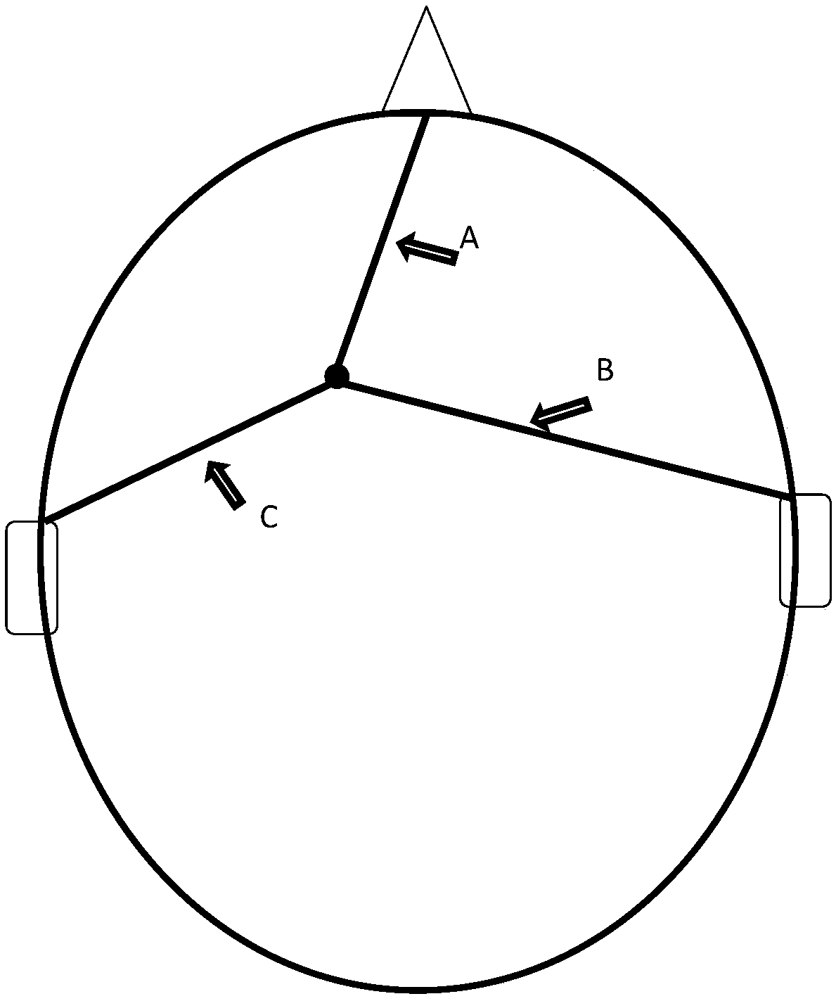
[0019] (3) Based on the magnetic resonance image, calculate the shortest distance between the patient's nasion root, the lowest point of the left and right ears and the scalp target point on the scalp surface in the image, and record them as A, B, and C centimeters respectively;

[0020] (4) Use a soft ruler to draw a circle on the scalp with the root of the nose and the lowest point of the left and right ears as the center, and A, B, and C cm as the radius. The intersection of the three circles is the scalp target point.

[0021] Such as figure 1 As shown, a group of number...

Embodiment 2

[0023] A transcranial magnetic stimulation target positioning method, comprising the following steps:

[0024] (1) Obtain the brain magnetic resonance scan image of the patient;

[0025] (2) Based on the magnetic resonance image, the nearest projection point of the area to be stimulated in the brain in the image is found by calculation, and the nearest projection point is called the scalp target point;

[0026] (3) Based on the magnetic resonance image, calculate the shortest distance between the patient's occipital protuberance, bilateral eye canthus and the scalp target on the scalp surface in the image, and record them as D, E, and F cm respectively;

[0027] (4) Use a soft ruler to draw a circle on the scalp with the center of the occipital prominence and the corners of both eyes, and the radius of D, E, and F centimeters. The intersection of the three circles is the scalp target.

[0028] A set of numbers (D, E, F) formed by the distance from any point on the head to the...


PUM


Abstract

The invention relates to the field of medical detection, and specifically relates to a transcranial magnetic stimulation target positioning method. The method comprises the following steps: (1), obtaining a craniocerebral magnetic resonance scanning image of a patient; (2), finding a nearest projection pint of an intracerebral to-be-stimulated region on head skin from the image through calculationbased on the magnetic resonance image, wherein the nearest projection pint is called as a head skin target; (3), calculating the nearest distances between at least three mark points on the face of the patient and the head skin target on the head skin surface in the image based on the magnetic resonance image; (4), enabling a flexible rule to take each mark point as the circle center and take thedistance between each mark point and the head skin target as the radius for drawing a circle on the head skin, wherein the intersection point of the circles is the head skin target. The method mainlydepends on the calculation of the cambered surface distance of each mark point on the transcranial magnetic resonance image, so the method is simple and convenient, does not need large-scale equipment, and exerts low requirements for a treatment place. Moreover, compared with a navigation system, the method greatly reduces the cost.

Description

technical field [0001] The invention relates to the field of medical detection, in particular to a transcranial magnetic stimulation target positioning method. Background technique [0002] Transcranial Magnetic Stimulation (Transcranial Magnetic Stimulation) is a non-invasive neurological intervention technique. Based on the principle of electromagnetic mutual conversion, the rapid charging and discharging of the stimulation coil will generate a time-varying induced magnetic field, and the time-varying magnetic field will generate an induced electric field and an induced current in the human tissue, thereby stimulating or controlling the neuron activity in the brain tissue. Inhibitory regulation. The human brain can be divided into multiple functionally specialized subregions. In order to regulate the functional activity of an abnormal brain region without affecting other normal brain regions, it is clinically necessary to find the body surface projection position of a s...

Claims


Application Information

Patent Timeline
IPC IPC(8): A61N2/04
CPCA61N2/006A61N2/02
Inventor 季公俊汪凯
Owner 安徽安壹心理咨询有限公司
Learn More