
Jet accumulation point gas-liquid separator

A technology of gas-liquid separator and gathering point, which is applied in the field of separation of solid-phase powder and liquid-phase mist, and achieves the effect of simple and compact structure, high separation efficiency and broad market prospect

Active Publication Date: 2018-03-20
佛山市东山瑞泽环保机器有限公司
View PDF6 Cites 4 Cited by
  • Summary
  • Abstract
  • Description
  • Claims
  • Application Information

AI Technical Summary

Problems solved by technology

Compared with the existing technology, it is simple and easy to use, more scientific and reasonable, and can stably solve the problem of oil mist collection and purification in the above-mentioned oil mist mixed gas, especially in the environment of relatively harsh oil mist working conditions

Method used


Image

  • Jet accumulation point gas-liquid separator
  • Jet accumulation point gas-liquid separator
  • Jet accumulation point gas-liquid separator

Examples


Embodiment Construction

[0017] The technical solutions of the present invention will be further described below in conjunction with the accompanying drawings and through specific implementation methods.

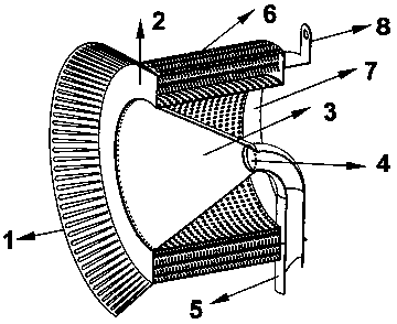
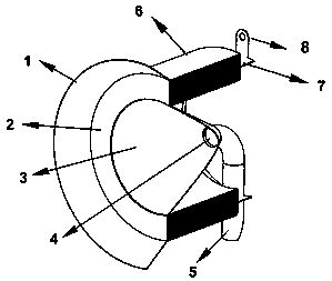
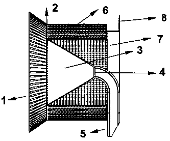
[0018] A jet gathering point gas-liquid separator, such as Figure 1-6 As shown, it includes a cylindrical filter 6 with holes at both ends. Filling), with one end face 2 of the cylindrical filter (the surface formed by the outer edge line and the inner edge line of the end face 2 can be in the same plane, or the inner edge line can be shrunk toward the inside of the filter, and the similar cone shape that is not on the same plane Structure) The outer edge line expands outwards and expands into a conical absorption mouth surrounding layer 1, and there are pores on the surrounding layer 1, and the end surface shrinks into the filter along the edge of the inner hole of the filter to form a funnel structure layer 3 , there is a through hole at the central point of the structure, that is, the liquid di...


PUM


Abstract

The invention relates to a jet accumulation point gas-liquid separator which comprises a cylindrical filter with through holes formed in the two ends; the outer edge line of one end surface of the cylindrical filter are expanded outward to form a conical absorption hole surrounding edge layer; holes are formed in the surrounding edge layer; the end surface shrinks inward along the inner hole edgeline of the filter to form a funnel structure layer; a through hole, i.e. accumulation point liquid drainage through hole, is reserved in the center of the structure; a liquid drainage elbow with an equal diameter with the through hole is arranged at the through hole connection part; and a cylinder wall which is smaller than the excircle of the filter and larger than the inner circle of the filteris arranged at the other end of the cylindrical filter. The jet accumulation point gas-liquid separator provided by the invention overcomes the technical defects that the conventional previous-stagefilter is fragile in expression and easy in saturated blockage when oil liquid in a mist is high in particle proportion and large in viscosity in severe oil mist treatment environment and reaches thepurpose of capability of realizing gas-liquid separation during initial treatment to enable the oil mist collection device to wholly keep constant beneficial running effect.

Description

technical field [0001] The present invention relates to the technical fields of oil mist separation, oil mist collection, and oil fume collection, and in particular to a device for separating liquid-phase mist and solid-phase powder mixed in gas. Background technique [0002] In the field of metal processing, a large amount of oil mist and smoke are generated during the operation of various types of production and processing equipment, and there is also a phenomenon of sticky matter synthesized by wetted solid powder in the mixed gas, some of which are The viscosity of oil is very high and the concentration of oil particles is relatively high, which brings great difficulties to the effective collection and treatment of oil mist and oil fume. [0003] In the summary of many years of practice in this field, it is found that the solutions adopted by the existing technology in dealing with the oil mist collection and purification treatment with the above-mentioned oil mist chara...

Claims


Application Information

Patent Timeline
Patent Type & Authority Applications(China)
IPC IPC(8): B01D50/00
CPCB01D50/20
Inventor 俞春华
Owner 佛山市东山瑞泽环保机器有限公司
Learn More